Snowblowers Owners Manual Parts List for 87D (87” Double Auger) Snowblower M K Martin Enterprise 3950 Steffler Rd Elmira Ont N3B 2Z3 (519) tel 664-2752 / fax 664-3695 E-mail: sales@mkmartin.
87D Meteor Snowblower Table of Contents 1. Registration and Warranty 2. Safety Introduction 3. Safety 4. Decal Location 5. Sign Off Form 6. Assembly Information 7. Operation 8. Installing manual Chute Rotator 9. Installing Hydraulic Chute Rotator 10. Main Parts 11. Chute Rotator Parts 12. Gearbox Parts 13. Comer PTO Parts 14. Canimex PTO Instructions 15. Bolt Torque 16.
Welcome to our lineup of Meteor Snowblowers M K Martin Enterprise Inc has been building the Meteor Snowblowers since 1985. With proper care and maintenance the Meteor Snowblower will give you years of reliable service. The most common damage to a Snowblower is from foreign objects. Please ensure that the area to be cleared of snow has been cleared of articles before the first snow falls. This gives you peace of mind and the assurance that you won’t get damaging objects into your blower.
Safety Take Note! This safety symbol is found throughout this manual to call your attention to instructions involving yourself and others working around the machine. • Failure to follow these instructions can result in injury or death! This symbol means --Attention! --Become Alert! --Your Safety is involved! Signal words are used in this book. Caution: Indicates a potentially hazardous situation that may result injury.
Safety – It’s in your interest. Safety Guidelines. Safety of the operator is one of our main concerns, however it is up to the operator to practice caution. To avoid personal injury, study the following precautions and insist that those working with you to follow them. The Meteor Snowblower has only 2 shields, one shield is the PTO drive shield and the other is a shield for the power hood turner if used. Do not use the blower with the auger drive cover removed, as this is part of the blower frame.
Sign-Off Form M. K. Martin Enterprise Inc. follows the general Safety Standards specified by the American Society of Agricultural Engineers (ASAE) and the Occupational Health and Safety Administration (OSHA). Anyone who will be operating and/or maintaining the Cutter must read and clearly understand ALL Safety Operating and Maintenance presented in his manual. Do not operate or allow anyone else to operate this equipment until such information has been reviewed.
5-108 Meteor Snowblower Assembly Information 1. 2. 3. 4. 5. 6. 2 set Hood Bearing Assembly 4 pc 5/8 Wavewasher (thin) 2 pc 5/8 x 2 UNF Bolts 2 pc 5/8 UNF Locknut 1 pc 2 hole Chute Clamp 1 Assembly Instructions Upon Receiving the Meteor Snowblower The blowers are shipped in a packaged state These blowers are packaged without hood turner device. Carefully remove the chute and PTO shaft from the area of the auger and set them aside. Locate the bag or package of small components.
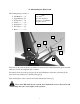
75-108 Installing the Hand Crank The Crank package consists of Bolts 2 pc 3/8x1 2pc 3/8 Lockwasher 2pc 5/8 x 2 1/4 UNF Bolt to replace 5/8 x 2 Tail Bracket --- (1) Upper Bracket- (2) Worm Gear ---- (3) Crank ----------- (4) Spring Pin ------ (5) Set Screws ----- (6) Bolts ------------ (7) 4 3 7 2 5 7 6 1 First remove the 2 nuts and bolts (as indicated), and insert the Crank Tail bracket[1] and reinstall with 5/8 x 2 1/4 bolts (supplied) and Locknuts.
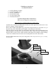
Hydraulic Rotator (Accessory) The hydraulic chute rotator uses a hydraulic motor, controlled by the tractor hydraulics to rotate the chute. The kit includes a safety shield that also keeps the snow and ice form building up on top of the gears. The motor kit is bolted to the base with 2, 1/2-20 UNF bolts. The shield is mounted with 4, 5/16 bolts as shown.
87D Meteor® Snowblower This Blower is ideal for tractors 60 HP Cat #2 3PH. Attaching the Meteor® Blower for the first time. Set the blower on a level surface and back the tractor up to it. Place the lower 3PH arms of the tractor between the lower hitch plates on the blower and insert the hitch pins that came with the blower, secure these with the Lynch Pins. Next swing the top link into place and adjust the length so the top link pin can be inserted. You will have to supply the top link pin.
Operating the Meteor® Snowblower This blower is on the back of the tractor facing toward the rear. While blowing snow the tractor has to be backed into the snow. Stay in the seat of the tractor all the time that the blower is running. Make sure the area is clear of people while blowing snow. Do not direct discharged snow toward people, cars or buildings as stones or bits of ice can go a long distance.
87D Meteor Parts Item No 1 2 3 4 5 6 7 8 9 10 11 87D Meteor Snowblower Description Main Body Fan Hexbolt 5/8x1 1/2 #2 c/w lw Chute Deflector Hinge Pin Cotter Pin 1/8x1 Hair Pin 5/32 Adjuster Adjuster Pin Antifriction Ring Part No 519-8711505D 519-87115208 OL 519-87116009 519-87115608 519-87115808 OL OL 519-871155 519-871154 519-871161 11 Req 1 1 1 1 1 1 1 2 1 1 1
45 46 47 48 87D Meteor Snowblower Description 3 Hole Chute Clamp 2 Hole Chute Clamp Hexbolt 1/2x2 unf c/w ln 5/8 Wave Washer 5/8 Bearing Auger Auger Sprocket Complete Bearing Bearing Insert Only Cast Flange Only Hexbolt 1/2x1 1/2 c/w n, lw Hexbolt 1/2x1 1/2 c/w n, lw Auger Drive Chain Hexbolt 5/8x4 c/w n, lw Flatwasher 3/4" Spacer Idler Sprocket Cross Shaft Auger Shear Sprocket Flangette Bearing 5/16x1 1/4 c/w ln Hexbolt 3/8x1 c/w n,lw Cross Shaft Shield Hexbolt 3/8x1 c/w n, lw Fan Key 3/8 sq x 3 5/8 Gearb
87-97 Meteor Chute Rotator Manual Chute Rotator 2010 Item No 1 2 3 4 5 6 7 8 Manual Rotator Description Crank Tail Bracket Upper Hand Crank Bracket Crank Crank Worm 5/16x1 1/2 Spring Pin 5/16x3/4 sq h Setscrew 5/8-11x2 1/2 Bolt c/w ln 3/8x1 1/4 Bolt c/w n, lw 13 Part No 519-87719109 519-87109009 519-68109109 519-68719209 OL OL OL OL Req 1 1 1 1 2 2 2
Hydraulic Chute Rotator 2010 Item No 1 2 3 4 5 6 7 8 9 10 11 12 13 14 Hydraulic Rotator Description Motor Bracket Motor O Ring 3/32x.
75 – 87 – 87D - 97 Meteor Snowblower Main Gearbox Item 1 2 3 4 5 6 7 8 9 10 11 12 13 14 15 16 17 18 19 20 21 T 27D Gearbox Description Part # Double Lip Seal 40x80x12 519-87100748 Snap Ring 519-85200030 Bearing 30208 519-80900024 Shim 515 519-02447500 Gear Z18 M6.15 519-01325002 Gear Z18 M6.15 519-02675000 Plug 519-86500006 Cover 519-02671300 Bolt M10 x 14 519-81101031 Shim 79.
Comer T50 PTO 40 Item # 1 2 30 31 33 37 38 40 61 71 72 73 200 Description Complete Collar Yoke Cross Journal Assy Complete Shear Yoke Guard Retaining Collar for Outer Tube Special Plastic Bolt Guard Retaining Collar of Inner Tube Safety Chain Complete Guard with Instruction Manual Special Grease Nipple Bolt & Nut M10x55 cl. 8.8 Grease Fitting Bolt & Nut M12x1.25x70 cl. 8.8 Collar Kit for 1 3/8" Yoke Danger Label for Outer Tube Danger Label for Outer Guard Tube PTO Instruction Manual 16 Part# 141.025.
PTO Installation Instructions for Snowblower 17
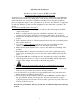
PTO Installation Instructions for Snowblower For Better PTO Shaft and Gearbox Operation A proper initial installation will give you years of satisfactory service on your equipment. Please read carefully, following instructions which have been specially made to help you and make you satisfied of your purchase. Warning! Unfortunately, snowblowers will be faced with forgotten or hidden objects under the snow, such as: chain, tires, stones, pieces of wood, etc.
Previous examples clearly demonstrate that universal joint angle is directly related with life of PTO. In order to reduce angle, it is necessary to increase the angle between snowblower and tractor. Too Large Angles at PTO Joints To Avoid Reasonable Angles at PTO Joints Acceptable If it is impossible to increase the distance between snowblower and tractor, in order to maintain a reasonable angle at the PTO, it is recommended to use a larger size PTO that is a greater capacity PTO.
Shear Bolts Shear bolts are built to break under shock loads on the fan or auger. However under certain circumstances this security is not adequate. Example: a sudden high impact shock on the fan may, in some cases break the fan shaft without breaking the shear bolt.
Effective PTO Drive Shaft Maintenance 21
Avoidable Damage Quick-disconnect yoke Quick-disconnect pin tight or completely seized Quick-disconnect pin damaged (broken or bent) Quick-disconnect pin damaged in locking position Possible Causes Quick-disconnect pin dirty (insufficient maintenance) Quick-disconnect pin defective (forced into place, incorrect handling.
Avoidable Damages Cross Kit Possible Causes Cross Arms broken Corrective Actions Extreme torque peak or shock load Use appropriate safety device Change to a larger PTO size Axial loads too large Shorten PTO shaft Replace defective cross bearings Bearing caps turning in their cross journal Excessive continuous torque and/or excessive working angle Verify compatibility between shaft and working conditions Overheated bearing caps Inadequate greasing Carefully follow greasing instructions Accelera
Avoidable Damages Shield Excessive wear of shield bearings Possible Causes Corrective Actions Insufficient lubrication Shield interfering with implement Follow lubrication instructions Mount chain to allow maximum angularity Avoid shield contact with machine or tractor Replace shield bearings Avoid shield contact with machine or tractor Incorrect chain mounting Mount chain to allow for maximum angularity Incorrect chain mounting Shield interfering with implement Chain failure Replace defective par
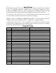
Bolt Torque As used on this equipment Bolt torque table shown below gives torque values for the various bolts used. This chart is for non-lubricated threads. Replace with the same strength bolt. Torque Specifications. Torque values are identified by their head markings Diameter “A” 1/4 5/16 3/8 7/16 1/2 5/8 3/4 1 SAE 2 Lb-ft 6 10 20 30 45 95 165 225 N.m (8) (13) (27) (41) (61) (128) (225) (345) SAE 5 Lb-ft 9 19 33 53 80 160 290 630 N.
87D Meteor Snowblower Maintenance • PTO Shearbolt – M10x50 - - 8.8 • Auger Shearbolt – 5/16 x 1 1/4” Gr #2 • Auger Drive Chain Tightener – tighten chain allowing ¼” sag in the bottom span of chain (between drive and driven sprocket). Lubrication • Gearbox- check oil level every 50 hours. Fill to oil level plug (middle of gearbox) with SAE 90 gear oil. SAE 80W90 gear oil may also be used. • Auger and Shear Sprocket Bearing – grease sparingly every 50 hours.