
User's Manual

© 2017 M-Labs Technologies LLC 7 / 15
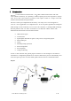
The LTE
provides support for specialized hardware features through extended AT
commands. The features supported include the following:
GPS
GPS location functionality is provided by the device GPS receiver. NMEA GPS records can be
extracted in real time from the unit via the UART connection using special debug commands
that are outside the scope of this document.
GPIO
One dedicated input, two dedicated outputs, and one general purpose IO are presented to the
external
environment
on the main connector. They are capable of providing system interrupts to
generate a report or drive logic levels to external devices. These lines are 2.8V logic level and
are 16V tolerant. These pins default to input and are pulled down representing 0 when
disconnected. They should be asserted to a known value if used.
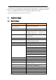
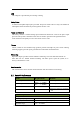
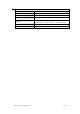
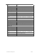
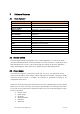
LED’s
Two LED status indicators are provided to verify correct installation and operation. The status
LEDs are color coded and directly convey the status of the cellular and GPS subsystems as
described in the table below. Their valid operation also indicates operational status and power.
LED Function Status
Red GPS
On: GPS satellites acquired and Locked
Flash Slow: GPS satellite search is in progress
Off: No power or GPS subsystem fault
Green Cellular
Connection
On: Indicates LTE connection is made
Flash Slow: LTE subsystem initialization in progress
Flash Fast: LTE initialization but no data connection available
Off: No power or LTE subsystem fault
The LTE
provides user control allowing the LEDs to be extinguished once installation is
verified. This feature reduces power and further conceals the LTE
Tracker from untrained
parties wishing to defeat its operation.
UART
There are two UART’s provided. A debug UART port is provided for AT commands, data
interaction and optionally for application specific control. A second, application UART is
provided to be used as an expansion port for sensors and other peripherals