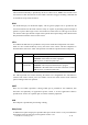
User Manual For LTE-V LTE-VB LTE-V -BA LTE-VB -BA Vehicle Tracking Device April 15, 2017 R1.
Author Revision Changes Date Zeev 1.
Contents 1 Introduction ...................................................................................................................................... 4 2 Hardware Design ............................................................................................................................ 5 2.1 Basic Hardware....................................................................................................................... 5 GPS ..............................................................
1 Introduction The LTE-V and derivatives are self-contained vehicle tracking device that combines GPS location with LTE CAT1 cellular connectivity. It is primarily a location reporting device that responds to requests (user, server) and events (timers, geo-fences). Data reports consist of a single record that contains all location data and system status. The device comes pre-configured from the factory. It is ready to use. The LTE-V appears to a user or a server application as an endpoint device.
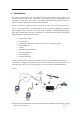
data/SQN3223) baseband module, which includes an ARM CPU, 4M serial flash, LTE_B2&B4&B12 RF transceiver, and triple-band RF front end circuit. Antennas for cellular and GPS are internal to the device. 2 Hardware Design 2.
GPS GPS location functionality is provided by the device GPS receiver. NMEA GPS records can be extracted in real time from the unit via the UART connection using special debug commands that are outside the scope of this document. GPIO One dedicated input, two dedicated outputs, and one general purpose IO are presented to the external environment on the main connector. They are capable of providing system interrupts to generate a report or drive logic levels to external devices. These lines are 2.
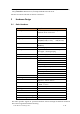
Power and Battery The battery monitor is internal analog input scaled such that the DC value of the power input pin to the LTE-V system is measured. This value is scaled to span the most significant 8 bits of the A/D and consequently covers a scale from 0 to 25.5 Volts. Timers Timers resident on the baseband chip generate periodic interrupts for power down wakeup, watchdog support, periodic report generation and other timer related functions. Watchdog SQN3223 chipset provides internal software Watchdog.
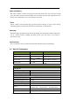
EVM <3% LTE_B13_RX Frequency range 746MHz ~ 756MHz Sensitivity -100dBm (10MHZ_50RB_Downlink) -23 ~ -100dBm Dynamic range LTE_B13 _TX Frequency range 777MHz ~ 787MHz Maximum Frequency error ±10Hz 23dBm <-40dBm UTRA2: 45.48 UTRA1: 41.41 UTRA2: 44.87 UTRA1: 41.51 8.87MHZ (10MHZ Nominal) < -54.7dbc <3% Maximum output power Minimum control output power ACLR OBW IQ OFFSET EVM E-UTRA1:39.43 E-UTRA2:38.25 GPS Frequency Support Sensitivity Tracking Time Requirement 2.3 L1-band (1.
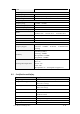
3 Software Features 3.1 Basic Software Items Requirement Network Interface IP Stack Upgrade Method Remote Update Power Modes AT Commands Report Drivers GPIOs LTE B4, B13 IPV4/IPV6 Remote update/ PC tool Supported – including OMA DM Supported Supported LEDs Watch Dog Reset Startup Banner GPS Status, Network Status Supported Soft reset, hard reset, GPS reset, RF reset Supported Supported: 3000 records GPIO,LED,GPS,UART, USB Accelerometer Interrupt for Ignition Status, Buzzer, Relay 3.
• • • Power-up Ignition Trip start and stop Any hardware or software reset will return the device to full power mode. 3.4 AT Commands Extended AT commands are specific to the LTE-V device. They are closely based on commands that are as similar as possible industry common devices and are essentially subsets of standard LTE-V commands. Native AT commands supported by the SQN3223 modules are also available via the serial and USB interfaces. Command Summary The following commands are specific to the LTE-V.
22. AT+IONNR: Set time before IP session is closed and restarted 23. AT+IONNW: Set watchdog timeout if no network found 24. AT+IONPM: Set auto power down mode 25. AT+IONRF: Report Format – Binary 26. AT+IONRI: Set report timer interval 27. AT+IONRM: Report Mask 28. AT+IONRN: Queue report record for transmission 29. AT+IONRR: Set reset report 30. AT+IONRS: Reset setting - soft/hard, periodic 31. AT+IONSD: Set SMS response destination 32. AT+IONSI: Set interrupt 33. AT+IONSQ: Set queue length 34.
queued, the reports will attempt to be sent in the order of triggering and only once the report is acknowledged, the next report is attempted. This assures that reports are sent and received in order Ack’ed mode assures that all reports are received, but adds overhead in time and data. Report that is not acknowledged is sent again and eventually will be queued and sent again. The number and frequency of re-tries is configurable via the Report Acknowledgement command. 3.
4 Test Method 4.1 Hardware Test Item Description Baseband Function Test • • • • • • • • • • Power Input Test Power Consumption and Current Test Heat Dissipation Test UART Stability Test GPIO Level Test LED Stability Test Drop Down Test ESD Test High/Low Temperature Test Humidity Test RF Test • • • RF Performance Test GPS Performance Test Antenna Performance Test 4.2 Software Test Test Environment Construct Message Test environment 1. USB dongle and PC as message server 2.
Mechanical Structure (mm) © 2017 M-Labs Technologies LLC 16 / 15
FCC Statement This equipment has been tested and found to comply with the limits for a Class B digital device, pursuant to Part 15 of the FCC Rules. These limits are designed to provide reasonable protection against harmful interference in a residential installation. This equipment generates uses and can radiate radio frequency energy and, if not installed and used in accordance with the instructions, may cause harmful interference to radio communications.