
User Manual

5
2. Recommendations for remote displays (sign boards) or data loggers.
• Look at the Approaching Target byte. If it is 4 or above, display it.
• If messages are not arriving, blank screen after a few seconds. The radar is probably off, or not
connected.
• Displaying the difference between the sign receiving a speed of zero and not receiving a message
at all is recommended. This makes troubleshooting easier. We display a dot if communications
are working properly.
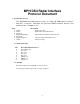
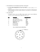
3. Pin out Description
Following is the pin out for the DS4 circular output connector (male bulkhead
connector on the module) with the mating cable wire colors:
Pin
Description Cable Wire Color
1 +13.6 VDC Input Red
2 OFF/ (Gnd to turn unit off) White
3 RS232 Rec Line (not used) Blue
4 RS232 Trans Line Brown
5 Signal Gnd Green
6 No Connection Orange
7 No Connection Yellow
8 Power Ground Black
DS4 CONNECTOR PIN DEFINITION
Guide Key
0
1
2
3
4
5
6
7
8