
Operating instructions


CONGRATULATIONS!
Your purchase of an M&S music system is an investment that will provide years of enjoyment and service for your
customer. M&S audio products are backed with more than 40 years of experience in the design and manufacture of
precision acoustical equipment for the home. To ensure that your customer receives the high-quality music and voice
reproduction that the system is designed to deliver, it is important that each step of the installation be done carefully. If
you follow the step-by-step illustrated instructions below, the result will be a successful professional-quality installation.
In the event you need troubleshooting assistance, please call our technical staff at 1-800-421-1587.
INSTALLATION INSTRUCTIONS
FINISH-OUT MC960 SYSTEM
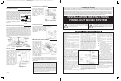
The exclamation point within an equilateral triangle is intended
to alert the user to the presence of important operating
and maintenance (servicing) instructions in the literature
accompanying the product.
The lightning fl ash with arrowhead symbol within an
equilateral triangle is intended to alert the user to the presence
of uninsulated “dangerous voltage” within the product’s
enclosure that may be of suffcient magnitude to constitute a
risk of electric shock to persons.
Read instructions - All the safety and operating
instructions should be read before the appliance
is operated.
Retain instructions - The safety and operating
instructions should be retained for future
reference.
Heed warnings - All warnings on the appliance
and in the operating instructions should be
adhered to.
Follow instructions - All operating and use
instructions should be followed.
Water and moisture - The appliance should not
be used near water - for example; near bathtub,
washbowl, kitchen sink, laundry tub, in a wet
basement, or near a swimming pool, and the
like.
Attachments - Do not use attachments not
recommended by the product manufacture
as they may cause hazards.
Ventilation - The appliance should be
situated so that its location or position does
not interfere with its proper ventilation. For
example, the appliance should not be
situated on a bed, sofa, rug, or similar
surface that may block the ventilation
openings: or, placed in a built in installation,
such as a bookcase or cabinet that may
impede the fl ow of air to the ventilation
openings.
Heat - The appliance should be situated
away from heat sources such as radiators,
heat registers, stoves, or other appliances
(including amplifi ers) that produce heat.
Power sources - The appliance should be
connected to a power supply only of the type
described in the operating instructions or as
marked on the appliance.
Grounding or polarization - Precautions should
be taken so that the grounding or polarization
means of an appliance is not defeated.
Power lines - An outdoor antenna should be
located away from power lines.
Outdoor antenna grounding - If an outside
antenna is connected to the receiver, be sure
the antenna system is grounded so as to provide
some protection against voltage surges and built
up static charges. Section 810 of the National
Electrical Code, ANSI/NFPA No. 70 1984,
provides information with respect to proper
grounding of the mast and supporting structure,
grounding of the lead in wire to an antenna
discharge unit, size of grounding conductors,
location of antenna discharge unit, connection
to grounding electrodes, and requirements for
the grounding electrode. See Figure below.
Object and liquid entry - Never push objects
of any kind into this product through openings
as they may touch dangerous voltage points
or short out parts that could result in a fi re or
electric shock. Never spill liquid of any kind on
the product.
Servicing - The user should not attempt to
service the appliance beyond that described in
the operating instructions. All other servicing
should be referred to qualifi ed service
personnel.
Damage requiring service - The appliance
should be serviced by qualifi ed service
personnel when:
■ The power supply cord or the plug has
been damaged; or
■ objects have fallen, or liquid has been
spilled into the appliance; or
■ The appliance has been exposed to
rain; or The appliance does not appear
to operate normally or exhibits a
marked change in performance; or
■ The appliance has been dropped,
or the enclosure damaged.
■ When the product exhibits a
distinct change in performance
- this indicates a need for service.
Replacement parts - When replacement
parts are required, be sure the service
technician has used replacement parts
specifi ed by the manufacturer or have the
same characteristics as the original part.
Unauthorized substitutions may result in
fi re, electric shock, or other hazards.
Safety check - Upon completion of any
service or repairs to this product, ask the
service technician to perform safety checks
to determine that the product is in proper
operating condition.
Wall or ceiling mounting - The product should
be mounted to a wall or ceiling only as
recommended by the manufacturer.
SAFETY INSTRUCTIONS
ANTENNA HOOKUP
Carefully remove the master unit face panel insert and
disconnect the speaker attached to it. Suspend the master
unit from the wall housing by looping the third-hand wire
(green wire) over the hook at the
top of the housing. Connect the
FM dipole twin lead to the FM 300
Ohm terminals on the tuner
module. Connect the orange AM
antenna wire to the AM terminal
on the tuner module as shown in
fi gure 14.
REMOTE AMPLIFIER/WIRELESS
From the 1st Power Amp, wire the MS7XSC as shown in fi gure 11
to the 8 pin connector P4. Connect the MS2SXSC to the two
ROOM REMOTE screws terminals as shown in fi gure 15. Note:
Both the blue wire and the shield wire connect to the same
terminal. Install the MCRC wireless remote control receiver in the
wall housing behind the Control Panel as shown in fi gure 15 by
removing the adhesive backing and pressing the MCRC fi rmly in
place. Route the antenna wire through the hole provided in the wall
housing. Connect the MCRC to the Control Panel as shown in
fi gure 15.
DOOR CHIMES
Connect all Orange wires from the chimes button to the Common
terminal. Connect each
Yellow wire to each note
selection terminal. (Do not
connect more than one
Yellow wire per note
terminal.). Plug in the
chime module plug to the
4 pin connector labeled as
CHIME on the master unit.
Connect the orange &
yellow wire at each door
chime button. Set the
jumpers at P7 per chime
operation. See fi gure 16.
CONNECTING THE MCD6
Connect the Left/Right audio
RCA plugs from the MCD6 to
the AUX1 L/R jacks,
respectively. Connect the 2-
pin control cable from the
MCD6 to the jack on the
MC960 labeled CD
INTERFACE
OTHER SOURCES
Plug in the RCA phono plugs to the
jacks as marked for the source
equipment. The fi gure to the right
shows a typical installation using the
AWP/AWPRX audio wall plate
installation kit.
BEFORE YOU APPLY POWER!
After wiring has been
completed, double check
your connections and
then connect the power
cord from the TE1
transformer to the
Control Panel. Secure
the Control Panel to the
wall housing using the
screws provided.
Reconnect the master
speaker and reinstall
insert. Plug-in the power
cord for each Power Amp
to a 120VAC receptacle.
If you encounter any problems, recheck all connections and check
the troubleshooting procedure in the operating instructions. If
problems still persist, contact our technical assistance center at
800-421-1587.
CONTROL PANEL INSTALLATION
Figure 14 - Antenna
hookup
Figure 15
Figure 16
Figure 17 - MCD6 hookup
M&S SYSTEMS 2-YEAR "NO FAULT" LIMITED WARRANTY
M&S Systems, Inc. warrants for two years (2) all products to be free of
factory-caused defects in material and workmanship. M&S Systems,
Inc. will repair or replace, at its option, parts and materials at no
charge, regardless of the problem. This warranty extends to the original
purchaser of the product and to each subsequent owner of the product
during the term of this warranty. This NO FAULT warranty covers only
the liability described above, and does not include liability for incidental
or consequential damages. NOTE: Some states do not allow the
exclusion or limitation of incidental or consequential damages, so the
above limitation or exclusion may not apply to you.
115851 B
PRINTER’S INSTRUCTIONS:
INSTR,INSTL,FINISH-OUT,MC960 - LINEAR P/N: 115851 B - INK: BLACK - MATERIAL: 20 LB. MEAD BOND - SIZE: FLAT: 17.000” X 11.000”, FOLDED 8.500” X 11.000” - SCALE: 1-1 - FOLDING: 1-FOLD VERTICAL - SIDE 1 OF 2