
Instruction Manual

IT60SW5F
5-2-55, Minamitsumori, Nishinari-ku, Osaka 557-0063 JAPAN
Phone: +81(6)6659-8201 Fax: +81(6)6659-8510 E-mail: info@m-system.co.jp
EM-2433 P. 7 / 8
CHECKING ETHERNET CONNECTION
■ PREPARATION FOR NETWORK
Prepare PC, clients and other devices for the network.
1. Connect the unit and PC with a LAN cable.
2. Set PC’s IP address to 192.168.0. xxx (for example, 192.168.0.10) which does not duplicate with the unit. Then, set subnet
mask to 255.255.255.0. (The unit’s factory setting IP address: 192.168.0.1)
■ SETTING ON THE WEB BROWSER
1. Start the web browser. Enter the unit’s IP address after http:// in address bar. For the first-time connection, enter as shown
below using the factory setting IP address.
http://192.168.0.1/
Web browser (recommended): Microsoft Internet Explorer 11 or later
2. Enter user name and password. For the first time connection, enter “admin” in those fields.
3. For setting details, refer to the operating manual (EM-2431-B).
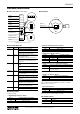
■ NETWORK CONNECTION
When the network is correctly installed and the connection is established, Link or Link100 LED turns ON or blinks.
■ CHECK TOWER LIGHT CONNECTION
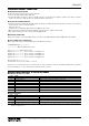
Enter “ping command” from Command Prompt on the Windows as follows:
C:¥WINDOWS>ping ***.***.***.***
(***.***.***.***: Enter IP address in decimal.)
ping ***.***.***.*** with 32 bytes of data:
Reply from ***.***.***.*** : bytes = 32 time < 10ms TTL = 64
Reply from ***.***.***.*** : bytes = 32 time < 10ms TTL = 64
Reply from ***.***.***.*** : bytes = 32 time < 10ms TTL = 64
Reply from ***.***.***.*** : bytes = 32 time < 10ms TTL = 64
Ping statistics for ***.***.***.***
Packets: Sent = 4, Received = 4, Lost = 0 (0% loss)
Replies in case of normal connection are as shown above. If the connection cannot be established normally due to problems
as wrong IP address, etc., other replies such as ‘timeout’ will be received.
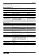
MODBUS FUNCTION CODES & SUPPORTED CODES
■ DATA AND CONTROL FUNCTIONS
CODE NAME
01 Read Coil Status Digital output from the slave (read/write)
02 Read Input Status Status of digital inputs to the slave (read only)
03 Read Holding Registers General purpose register within the slave (read/write)
04 Read Input Registers Collected data from the field by the slave (read only)
05 Force Single Coil Digital output from the slave (read/write)
06 Preset Single Registers General purpose register within the slave (read/write)
15 Force Multiple Coils Digital output from the slave (read/write)
16 Preset Multiple Registers General purpose register within the slave (read/write)
■ EXCEPTION CODES
CODE NAME
01 Illegal Function Unsupported function code
02 Illegal Data Address Unsupported address
06 Slave Device Busy Full request queue
11 Gateway Target Device Failed To Respond Error response from 900 MHz band wireless device (child) or time-out
Note: When 900 MHz band wireless device (child) returns an exception code other than the above, the exception code is transmitted
directly to upper devices.