
Instruction Manual

IT60SW5F
5-2-55, Minamitsumori, Nishinari-ku, Osaka 557-0063 JAPAN
Phone: +81(6)6659-8201 Fax: +81(6)6659-8510 E-mail: info@m-system.co.jp
EM-2433 P. 3 / 8
COMPONENT IDENTIFICATION
5
4
3
2
2
1
0
9
8
7
6
5
4
3
1
0
9
8
7
6
5
4
3
2
1
0
9
8
7
6
Mode
Power
Run
Link 920Link
Link100
920Run
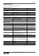
Antenna
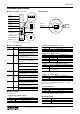
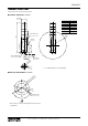
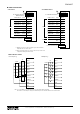
■ FRONT VIEW (with the cover open)
■ BOTTOM VIEW
PoE
*
1
Ethernet
Modular Jack
FRONT
Lamp 1
Lamp 2
Lamp 3
Lamp 4
Lamp 5
Status Indicator LED
Connector
for Maintenance
IP Address Reset
Buzzer Aperture
Gasket
Operating Mode Setting
DIP SW
*1. Equipped when PoE is selected
■ STATUS INDICATOR LED
ID COLOR FUNCTION
Power Green On when power is supplied.
Blinks when the IP Reset SW is on.
Off when power is not supplied or an
abnormality occurs in the unit.
Run Green On when Modbus/TCP communication
is in normal status.
(For Modbus node address 255 only)
Off at Modbus/TCP communication
error or during no Modbus/TCP com-
munication.
Link Green On when linking through 10 or 100
BASE.
Blinks when transmitting/receiving
data.
Off when there is no link.
Link100 Green On when linking through 100 BASE.
Off when linking through 10 BASE or
there is no link.
920Link Green On when wireless link is working.
Blinks with 0.5 Hz in establishing wire-
less link.
Off when wireless link stops working.
920Run Green On when wireless communication with
child device is in normal status.
Off at a wireless communication error
or during no communication.
PoE Green On when power is supplied via PoE.
Off when power is not supplied via PoE.
■ OPERATING MODE
(*) Factory setting
• Lamp Blinking Frequency: Mode-1
Mode-1 LAMP BLINKING FREQUENCY
OFF Approx. 2 Hz (*)
ON Approx. 10 Hz
• Buzzer Intermittent Frequency: Mode-2
Mode-2 BUZZER INTERMITTENT FREQUENCY
OFF Approx. 2 Hz (*)
ON Approx. 10 Hz
• Buzzer Volume: Mode-3, Mode-4
Mode-3 Mode-4 BUZZER VOLUME
OFF OFF Quiet (*)
OFF ON Middle
ON OFF Loud
ON ON Maximum
• Output at the Loss of Communication: Mode-6
Mode-6 OUTPUT AT THE LOSS OF COMMUNICATION
OFF Reset the output (turned off) (*)
ON
Hold the output (maintains the last data
received normally)
Available when ‘Input Select’ is set to Modbus/TCP.
• Output Logic Reverse: Mode-7
Mode-7 OUTPUT LOGIC REVERSE
OFF Non-inverted (*)
ON Inverted
Available when ‘Input Select’ is set to Discrete input.
Not available with blink (BLINK) or intermittence (BUZZ-
ER2), be sure to turn it off.
• Input Select: Mode-8
Mode-8 INPUT SELECT
OFF Modbus/TCP (*)
ON Discrete input
Selects the input signal of lamp and buzzer control.
Note: Be sure to set unused Mode-5 to OFF.
■ IP ADDRESS RESET
IP RESET SW IP ADDRESS RESET
OFF Operating (*)
ON IP address returns to factory default
Note: Other network settings are also reset to default.