
Instruction Manual

IT60SW5F
5-2-55, Minamitsumori, Nishinari-ku, Osaka 557-0063 JAPAN
Phone: +81(6)6659-8201 Fax: +81(6)6659-8510 E-mail: info@m-system.co.jp
EM-2433 P. 6 / 8
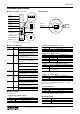
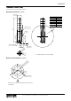
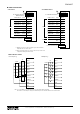
■ CONNECTION DIAGRAM
U (+)
V (–)
FE1
• PoE SUPPLY
INPUT
INPUT
LAMP 1 INPUT
LAMP 2 INPUT
LAMP 3 INPUT
LAMP 4 INPUT
LAMP 5 INPUT
BUZZER INP 1
Continuance
BUZZER INP 2
Intermittence
LAMP BLINK
COM
BUZZER1
BUZZER2
BLINK
LAMP1
*
1
LAMP2
*
1
LAMP3
*
1
LAMP4
*
1
LAMP5
*
1
Red
*
2
Amber
*
2
Green
*
2
Blue
*
2
White
*
2
LAMP1
*
1
LAMP2
*
1
LAMP3
*
1
LAMP4
*
1
LAMP5
*
1
Red
*
2
Amber
*
2
Green
*
2
Blue
*
2
White
*
2
COM
Purple
Cyan
Brown
Orange
LAMP 1 INPUT
LAMP 2 INPUT
LAMP 3 INPUT
LAMP 4 INPUT
LAMP 5 INPUT
BUZZER INP 1
Continuance
BUZZER INP 2
Intermittence
LAMP BLINK
COM
BUZZER1
BUZZER2
BLINK
COM
Purple
Cyan
Brown
Orange
Antenna Connector
RJ-45 Modular Jack
RJ-45 Modular Jack
Antenna Connector
USB Connector
Connector for maintenance
To other PoE supported
Ethernet devices
To other Ethernet devices
POWER
Gray
Black
Green/Amber
FE
Connector for maintenance
USB Connector
• DC POWER SUPPLY
*1. Example of 5 layers in order: red, amber, green, blue and white.
Lamp and wire color are the same.
*2. When selecting the same color for more than one layer, cable colors
comply with ordering information sheet.
LAMP1
LAMP2
LAMP3
LAMP4
LAMP5
BUZZER1
BUZZER2
COM
BLINK
LAMP1
LAMP2
LAMP3
LAMP4
LAMP5
BUZZER1
BUZZER2
COM
BLINK
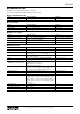
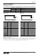
• WIRING TO INPUT SIGNAL
Contact input e.g.
NPN input e.g.
BLINK
ON
TOWER LIGHT TOWER LIGHT
BLINK
ON
Note: If “On” and “Blink” are set simultaneously for a single lamp, “Blink” is disabled.
At this time, if other lamps are being set to "Blink", they are also affected and work in the same manner.