
Instruction Manual

5-2-55, Minamitsumori, Nishinari-ku, Osaka 557-0063 JAPAN
Phone: +81(6)6659-8201 Fax: +81(6)6659-8510 E-mail: info@m-system.co.jp
EM-2436 P. 1 / 8
INSTRUCTION MANUAL
PATLABOR
™
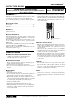
WIRELESS TOWER LIGHT
(small size, 60 mm dia., Modbus-RTU transparent 900MHz band wireless
device (child), 1 - 5 lay
ers)
MODEL
IT60SW6F
BEFORE USE ....
Thank you for choosing M-System. Before use, please check
contents of the package you received as outlined below.
If you have any problems or questions with the product,
please contact M-System’s Sales Office or representatives.
■ PACKAGE INCLUDES:
Tower Light .........................................................................(1)
Antenna ...............................................................................(1)
■ MODEL NO.
Confirm Model No. marking on the product to be exactly
what you ordered.
■ INSTRUCTION MANUAL
This manual describes necessary points of caution when
you use this product, including installation, connection and
basic maintenance procedures.
For information on the introduction of wireless device, refer
to the 900 MHz band wireless device operating manual
(EM-9085-B).
For information on Modbus specification, refer to the Mod-
bus Protocol Reference Guide (EM-5650).
These manuals are downloadable at M-System’s web site
(http://www.m-system.co.jp).
POINTS OF CAUTION
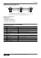
■ POWER INPUT RATING & OPERATIONAL RANGE
• Locate the power input rating marked on the product and
confirm its operational range as indicated below:
24 V DC rating: 24 V ±10%, approx. 7W
■ GENERAL PRECAUTIONS
• Before you remove the unit or mount it, turn off the power
supply and input signal for safety.
• The unit must not be subjected to external force.
• Do not rub the unit with organic solvent such as paint
thinner.
■ ENVIRONMENT
• Indoor use.
• Attach the antenna to the unit.
• Do not install the unit where it is subjected to continuous
vibration. Do not subject the unit to physical impact.
• Environmental temperature must be within -10 to +55°C
(14 to 131°F) with relative humidity within 10 to 90% RH
in order to ensure adequate life span and operation.
• Mount the unit on a flat and robust plate.
• Lamps are omnidirectional.
• The buzzer sound is directional in front of the unit.
• This unit communicates by radio waves. Do not install the
unit where it could be exposed to radio waves obstacles or
strong electric fields.
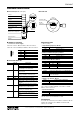
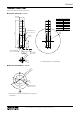
• How to change antenna angle: Rotate the antenna after
loosening the connector nut (refer to the next drawing).
Tighten the nut with torque (0.98 N·m) while holding the
antenna pointing to the intended direction. Otherwise,
tight manually the nut, and assure it turning 10° to 15°
more with a wrench.
Connector Nut
■ INGRESS PROTECTION (IP65)
• The IP code is conformable when the unit is mounted ver-
tically, antenna is installed and the control panel cover is
locked. The compartment, where connectors are located,
is not protected.
• When opening the control panel cover, avoid humidity
and dust penetration. Dry and clean it if condensation is
formed, and close the cover locking tightly.
• Install the antenna and tighten the connector nut tightly.
• In order to protect ingress of water or dust into the bot-
tom compartment, mount the unit on the flat plane, and
be sure that the gasket does not roll back or dust is not
on the gasket.
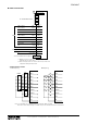
■ WIRING
• Do not install cables close to noise sources (relay drive
cable, high frequency line, etc.).
• Do not bind these cables together with those in which
noises are present. Do not install them in the same duct.
• Cables to the unit must be wired indoor.
■ AND ....
• The unit is designed to function as soon as power is sup-
plied, however, a warm up for 10 minutes is required for
satisfying complete performance described in the data
sheet.