
Instruction Manual

IT60SW6F
5-2-55, Minamitsumori, Nishinari-ku, Osaka 557-0063 JAPAN
Phone: +81(6)6659-8201 Fax: +81(6)6659-8510 E-mail: info@m-system.co.jp
EM-2436 P. 3 / 8
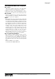
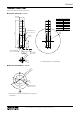
COMPONENT IDENTIFICATION
5
4
3
2
2
1
0
9
8
7
6
5
4
3
1
0
9
8
7
6
5
4
3
2
1
0
9
8
7
6
Mode
Power
Run
SD
920Link
RD
920ERR
920Run
Lamp 2
Lamp 3
Lamp 4
Lamp 5
Lamp 1
Status Indicator LED
Connector for
Maintenance/Configurator
Buzzer Aperture
Gasket
Antenna
Operating Mode Setting
DIP SW
■ FRONT VIEW (with the cover open)
■ BOTTOM VIEW
→
ON
RS-485
Connector
Te rminator SW
FRONT
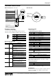
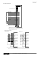
■ TERMINAL ASSIGNMENT
• Connector for Power Supply
Unit side connector: MC1,5/5-GF-3,5 (Phoenix Contact)
Cable side connector: FMC1,5/5-STF-3,5 (Phoenix Contact)
DA
DB
DG
SLD
FE
ID FUNCTION
DA DA
DB DB
DG DG
SLD Shield
FE Functional earth
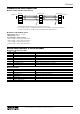
■ STATUS INDICATOR LED
ID COLOR FUNCTION
Power Green On when power is supplied.
Blinks when the IP Reset SW is on.
Off when power is not supplied or an
abnormality occurs in the unit.
Run Green On when Modbus communication is in
normal status.
Off at Modbus communication error or
during no Modbus communication.
SD Green On in sending data via RS-485
RD Green On in receiving data via RS-485
920Link Green On when wireless link is working.
Blinks with 0.5 Hz in establishing wire-
less link.
Off when wireless link stops working.
920Run Green On when wireless communication with
child device is in normal status.
Off at a wireless communication error
or during no communication.
920ERR Red On when there is no detour route.
Blinks at network authentication
failure.
Off in normal status.
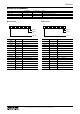
■ OPERATING MODE
(*) Factory setting
• Lamp Blinking Frequency: Mode-1
Mode-1 LAMP BLINKING FREQUENCY
OFF Approx. 2 Hz (*)
ON Approx. 10 Hz
• Buzzer Intermittent Frequency: Mode-2
Mode-2 BUZZER INTERMITTENT FREQUENCY
OFF Approx. 2 Hz (*)
ON Approx. 10 Hz
• Buzzer Volume: Mode-3, Mode-4
Mode-3 Mode-4 BUZZER VOLUME
OFF OFF Quiet (*)
OFF ON Middle
ON OFF Loud
ON ON Maximum
• Output at the Loss of Communication: Mode-6
Mode-6 OUTPUT AT THE LOSS OF COMMUNICATION
OFF Reset the output (turned off) (*)
ON
Hold the output (maintains the last data
received normally)
Available for Modbus communication.
• Output Logic Reverse: Mode-7
Mode-7 OUTPUT LOGIC REVERSE
OFF Non-inverted (*)
ON Inverted
Available for discrete input.
Not available with blink (BLINK) or intermittence (BUZZ-
ER2), be sure to turn it off.
• Input Select: Mode-8
Mode-8 INPUT SELECT
OFF Modbus/TCP (*)
ON Discrete input
Selects the input signal of lamp and buzzer control.
Note: Be sure to set unused Mode-5 to OFF.
■ TERMINATOR
To enable the terminator, turn ON the terminator SW. To
disable the terminator, turn OFF the terminator SW.
(Factory set to OFF)