
Instruction Manual

IT60SW6F
5-2-55, Minamitsumori, Nishinari-ku, Osaka 557-0063 JAPAN
Phone: +81(6)6659-8201 Fax: +81(6)6659-8510 E-mail: info@m-system.co.jp
EM-2436 P. 5 / 8
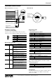
TERMINAL CONNECTIONS
Connect the unit as in the diagram below.
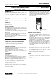
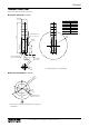
■ EXTERNAL DIMENSIONS unit: mm
A
192
224
256
288
320
352
Control Panel Cover
Antenna
(60)
Approx. 1500
Lead wires
R165
*1. Consult M-System for other bolt length.
0
1
2
3
4
5
Lamp Layers
60±1.5dia.
A±4
(85)
3 Bolts and Nuts (M4)
43 ±1.5 dia.
(30 dia.)
1– 6 lengths*
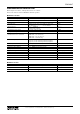
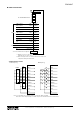
■ MOUNTING REQUIREMENTS unit: mm
120°
43 dia.
3 Holes (5 dia.)
Front
Wiring Hole 30 dia.*
* Protect wires to prevent scratching them at the edge of the
compartment.