
User's Manual


R3-NMW1F
5-2-55, Minamitsumori, Nishinari-ku, Osaka 557-0063 JAPAN
Phone: +81(6)6659-8201 Fax: +81(6)6659-8510 E-mail: info@m-system.co.jp
EM-8286 P. 10 / 10
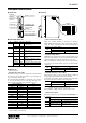
■ BCD DATA (32-bit data, models: R3-BA32A, BC32A, etc.)
32-bit binary data is used for BCD.
Lower 16 bits are allocated from the lowest address to higher ones, higher 16 bits in turn.
32-bit data cannot be accessed using floating addresses.
0
15
+0
Lower 16 bits
0
15
+1
Higher 16 bits
■ 16-POINT, DISCRETE DATA (models: R3-DA16 and DC16, etc.)
0
15
Input 1 (Output 1)
Input 2 (Output 2)
Input 3 (Output 3)
: :
Input 16 (Output 16)
0 : OFF
1 : ON
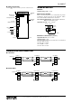
■ DUAL COMMUNICATION MODE
RS485 or wireless port set for Write enable port can be dual-redundant.
■ MAIN / SUB SWITCHING CONTROL
Address : 01025 = 0
Communication Status Start Main Lost Main Restored Switching by Host
Address : 01025 = 1
R3 main network
(main/sub switching control)
Address : 01025 = 0
Address : 01025 = 1
R3 sub network
(main/sub switching control)
(1) (2) (3) (4) (5)
1) When the main/sub switching control for both main and sub network is set to ‘0’, all contact outputs are off, and analog
output modules output -15%.
2) When the main’s setting is switched to ‘1’, the output modules are in control of the main host device.
3) When a loss of communication is detected in the main network, the output signal is held for the preset time period. (Timer
is programmable with the PC Configurator Software, R3CON.) After the time has elapsed, the output control is switched
from the main to the sub network. Be sure to set an appropriate output signal to the sub network and switch the sub’s
setting to ‘1’ before such switching occurs.
4) The output modules’ control is not automatically switched back to the main’s when the main network is restored if the
main’s setting is ‘0’. Thus, if the main’s setting is ‘1’, the control is back to the main’s.
5) When both the main and the sub network modules are in communication, the output can be switched without delay.