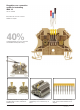
Pluggable cross-connection system for bestselling WDU 2.5 Cat. No. 102000 Blue, black and red cross connects available on request 40% of all terminal blocks are cross-connected. Considerable assembly time saving Touch safe protection according to VBG 4 and VDE 0106, Part 100 /3.
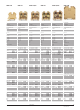
Feed-through terminal blocks Dimensions Width/length/height (mm) with TS 32 Y Width/length/height (mm) with TS 35 x 7.5 W Insulation stripping length/clamping screw VDE rated data. 0611 Part 1/8.
WDK 2.5 WDK 2.5/10 WDK 2.5 WDK 2.5 V WDK 2.5 DU-PE WDK 2.5 E WDK 2.5 EGET.SCH. 800 V Terminal blocks for electrical components 400 V Modular terminals with electronic components, see from page 1/112 – – 5/69/63 10 mm/M 2.5/3.5 x 0.6 – 6/69/63 10 mm/M 2.5/3.5 x 0.6 – 5/69/63 10 mm/M 2.5/3.5 x 0.6 – 5/69/63 10 mm/M 2.5/3.5 x 0.6 400 V/24 A/2.5 mm2 6 kV/3 800 V/24 A/2.5 mm2 8 kV/3 400 V/24 A/2.5 mm2 6 kV/3 400 V/-/24 A/-/2.5 mm2 6 kV/3 -/-/2.5 mm2 -/- 0.4...0.7 1 0.4...0.7 1 0.4...0.7 1 0.
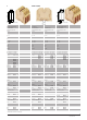
Feed-through terminal blocks Dimensions Width/length/height (mm) with TS 32 Y Width/length/height (mm) with TS 35 x 7.5 W Insulation stripping length/clamping screw VDE rated data. 0611 Part 1/8.
WDU 16N WDU 16 WDU 16/ZA* WDU 35 WDU 35/ZA* WDU 70N – 12/60/47 12 mm/M 4/5.5 x 1.0 – 12/60/63 16 mm/M 5/5.5 x 1.0 – 12/60/63 16 mm/M 5/5.5 x 1.0 – 16/60/63 18 mm/M 6/5.5 x 1.0 – 16/60/63 18 mm/M 6/5.5 x 1.0 20.5/75/93.5 20.5/75/86 22 mm/M 8/S 6 DIN 6911 400 V/76 A/16 mm2 6 kV/3 1000 V/76 A/16 mm2 8 kV/3 1000 V/76 A/16 mm2 8 kV/3 1000 V/125 A/35 mm2 8 kV/3 1000 V/125 A/35 mm2 8 kV/3 1000 V/192 A/70 mm2 8 kV/3 1.2...2.4 4 2.0...4.0 – 2.0...4.0 – 2.5...5.0 – 2.5...5.0 – 6.0...12 – 1.
Feed-through terminal blocks Large size conductors no longer have to be inserted into the clamping point with force; they can simply be placed in the terminal block. For each terminal type, terminal block variants consisting of three, four and fivepole terminal blocks are available in addition to the individual terminals. All blocks are permanently screwed together for additional rigidity. Slots provided in the underside of the terminal enable direct fitting.
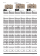
WDU 70/95/… WDU 120/150 WDU 120/150/… Template for direct mounting Template for direct mounting – 81/132/108 (triple block)* 30 mm/M 8/S 6 – 32/132/118 35 mm/M 10/S 6 32/132/127 – 35 mm/M 10/S 6 – 96/132/118 (triple block)* 35 mm/M 10/S 6 1000 V/192 A/70 mm2 8 kV/3 1000 V/269 A/120 mm2 8 kV/3 1000 V/269 A/120 mm2 8 kV/3 1000 V/269 A/120 mm2 8 kV/3 6...12 – 10...20 – 10...20 – 10...
Tab connection terminals WFF 35 WFF 70 # Y Dimensions Width/length/height (mm) Width/length/height (mm) with WAH covers Bolt size VDE rated data. 0611 Part 1/8.92/IEC 947-7-1 Rated voltage/rated current/rated cross-section Rated impulse voltage/pollution severity Further technical data Tightening torque range Clampable conductor Cable lug DIN 46 235 Cable lug DIN 46 234 2 x Cable lug DIN 46 235 2 x Cable lug DIN 46 234 Strips Strips Strips Gauge for flat connections to EN 50043 Cont.
WFF 120 WFF 185 # WFF 185 M 12 + M 16 Y W WFF 300 Y Template for direct mounting Y Y Template for direct mounting Y W Template for direct mounting Y W 42/132/72 42/230/81 10 42/132/81 42/230/89 10 55/163/78 55/287/91 12 55/163/86.5 55/287/99 12 55/163/86 55/287/90 16 55/163/94.5 55/287/99 16 1000 V/269 A/120 mm2 8 kV/3 1000 V/269 A/120 mm2 8 kV/3 1000 V/353 A/185 mm2 8 kV/3 1000 V/353 A/185 mm2 8 kV/3 1000 V/520 A/300 mm2 8 kV/3 1000 V/520 A/300 mm2 8 kV/3 10...20 10...20 14...
Coloured terminals Dimensions Width/length/height (mm) With TS 32 Y Width/length/height (mm) With TS 35 x 7.5 W Insulation stripping length/clamping screw VDE rated data 0611 Part 1/8.92/IEC 947-7-1 Rated voltage/rated current/rated cross-section Rated voltage/pollution severity Further technical data (see product pages) UL/CSA rated data Voltage/current/conductor size Voltage/current/conductor size Ordering data ● ● ● ● ● ● ❍ ● ● ● ● End plate/partition WAP (thickness 1.
Protective earth terminal blocks Dimensions Width/length/height (mm) with TS 35 x 7.5 W Insulation stripping length/clamping screw VDE rated data, 0611 Part 3/11.89 Rated voltage/rated current at PEN/rated cross-section Rated insulation voltage VDE 0110/2.79/Iso group C V~ Rated voltage/impulse voltage VDE0110/1.
Protective earth terminal blocks Dimensions Width/length/height (mm) with TS 35 x 7.5 W Insulation stripping length/clamping screw VDE rated data, 0611 Part 3/11.89 Rated voltage/rated current at PEN/rated cross-section Rated insulation voltage VDE 0110/2.79/Iso group C V~ Rated voltage/impulse voltage VDE0110/1.
Isolating neutral terminal blocks Dimensions Width/length/height (mm) with TS 32 Y Width/length/height (mm) with TS 35 x 7.5 W Insulation stripping length/clamping screw VDE rated data. 0611 Part 5/ 5.84 Rated voltage/rated current/rated cross-section Rated insulation voltage VDE 0110/2.79/Iso group C V~ Rated voltage/impulse voltage VDE0110/1.
Isolating neutral terminal blocks Dimensions Width/length/height (mm) with TS 32 Y Width/length/height (mm) with TS 35 x 7.5 W Insulation stripping length/clamping screw VDE rated data. 0611 Part 5/ 5.84 Rated voltage/rated current/rated cross-section Rated insulation voltage VDE 0110/2.79/Iso group C V~ Rated voltage/impulse voltage VDE0110/1.
Three-way terminal blocks Terminals / accessories WDL 2.5/S/ NT/L/PE WDL 2.5/S/ L/L L NT L L PE Installation specifications for power systems up to 1000V to VDE 0100 (EC 364) require that the installed system be subjected to an insulation measurement test.Special specifications stipulate an insulation measurement for all outgoing conductors(L 1, L 2, L3, N) without making any disconnections.The WDL three-way terminal block meets these requirements.
WDL 2.5/S-blocks WDL 2.5/S/N WDL 2.5/S/L WDL 2.5/S/ N/L for one three-phase circuit1) for three AC circuits 2) N WDL 2.5/S/ N/L/PE N L WDL 2.5/S/ L/L/PE N L L L L PE PE – 12/18/84.5/48.7 8 mm/M 2.5/3.5 x 0.6 – 6/84.5/48.7 8 mm/M 2.5/3.5 x 0.6 – 6/84.5/48.7 8 mm/M 2.5/3.5 x 0.6 – 6/84.5/48.7 8 mm/M 2.5/3.5 x 0.6 – 6/84,5/48,7 8 mm/M 2,5/3,5 x 0,6 – 6/84.5/48.7 8 mm/M 2.5/3.5 x 0.6 250V/400V/24 A/2.5 mm2 250/380 250V/400V/4 kV/3 400 V/24 A/2.5 mm2 250/380 400 V/6 kV/3 400 V/24 A/2.
Three Way terminal blocks Terminals/accessories WDL 2.5/NT/L/PE * WDL 2.5/L/L * NT L L L PE Installation specifications for power systems up to 1000V to VDE 0100 (EC 364) require that the installed system be subjected to an insulation measurement test. Special specifications stipulate an insulation measurement for all outgoing conductors(L 1, L 2, L3, N) without making any disconnections.The WDL three-way terminal block meets these requirements.
WDL 2.5/N * WDL 2.5/L * N WDL 2.5/N/L * L WDL 2.5/N/L/PE * N WDL 2.5/L/L/PE * N L L L L PE PE – 6/90/48.7 8 mm/M 2.5/3**/3.5 x 0.6 – 6/90/48.7 8 mm/M 2.5/3**/3.5 x 0.6 – 6/90/48.7 8 mm/M 2.5/3**/3.5 x 0.6 – 6/90/48.7 8 mm/M 2.5/3**/3.5 x 0.6 – 6/90/48.7 8 mm/M 2.5/3**/3.5 x 0.6 400 V/24 A/2.5/4** mm2 250/380 400 V/6 kV/3 400 V/24 A/2.5/4** mm2 250/380 400 V/6 kV/3 400 V/24 A/2.5/4** mm2 250/380 400 V/6 kV/3 250V/400V/24 A/2.5/4** mm2 250/380 250V/400 V/4 kV/3 250V/400V/24 A/2.
Disconnect test terminal blocks WTR 2.5 Dimensions Width/length/height (mm) With TS 32 Y Width/length/height (mm) With TS 35 x 7.5 W Insulation stripping length/clamping screw Rated data Rated voltage/rated current/rated cross-section Impulse voltage VDE 0110/1.
WDT 1.5/1 WDT 1.5/2 WDT 1.5/3 WDT 1.5/4/32 WDT 1.5/5/32 With space-saving TOPconnection With space-saving TOPconnection With space-saving TOPconnection With space-saving TOPconnection With space-saving TOPconnection Circuit diagram Circuit diagram – 6.5/112/67 10 mm/M 2.5/3.5 x 0.6 6.5/112/76 – 10 mm/M 2.5/3.5 x 0.6 – 6.5/112/67 10 mm/M 2.5/3.5 x 0.6 6.5/112/76 – 10 mm/M 2.5/3.5 x 0.6 6.5/112/67 – 10 mm/M 2.5/3.5 x 0.6 250 V/10 A/1.5 mm2 4 kV/3 250 V/10 A/1.5 mm2 4 kV/3 250 V/10 A/1.
Disconnect test terminal blocks Dimensions Width/length/height (mm) With TS 32 Y Width/length/height (mm) With TS 35 x 7.5 W Insulation stripping length/clamping screw Rated data Rated voltage/rated current/rated cross-section Impulse voltage VDE 0110/1.
Disconnect test terminal blocks Current transformers must always have a closed secondary circuit, even when the exchanging measuring instruments or electricity meters and when carrying out reference measurements with external measuring instruments. Various easy and clear wiring solutions can be found using lateral disconnect terminals WTL 6/1, feed-through terminals WTD 6/1 and cross-disconnect terminals WTQ 6/1.
Disconnect test terminal blocks WTQ 6/1 Dimensions Width/length/height (mm) with TS 32 Y Width/length/height (mm) with TS 35 x 7.5 W Insulation stripping length/clamping screw Rated data Rated voltage/rated current/rated cross-section Rated impulse voltage VDE 0110/1.
Meter test set with WTL 6/1 and WTD 6/1 Current transformer circuit configuration with WLT 6/1 and WTD 6/1 Sliding-link terminal and feed-through terminal combination Normal operation Current transformers must not be operated with an open circuit on the secondary side. This must be taken into account when changing measuring instruments or for comparative measurements with external instruments.
Current transformer circuit configuration with WTQ 6/1 With the WTQ 6/1, current transformer circuit configurations can be achieved quickly and clearly. The SSP 3 switch locking device helps to prevent incorrect operation. A A A 1 1 1 2 2 2 A 1 k 2 3 3 3 4 4 4 1 3 k I Normal operation Terminal 1 is separated from the shortcircuiting link by the open disconnect slide link; terminals 2 and 3 are short-circuited. Pos. ➀ ➁ ➂ ➃ 1/26 A Type Cat. No. WTQ 6/1 101790 Qty.
Linked current transformer test circuit Current transformer circuit configuration with four WTL 6/2 and staggered short-circuit links The WTL 6/2 ensures that an ammeter can initially be disconnected when the associated short-circuiting slider is closed, so that the current transformer is shortcircuited. In an open condition, the shortcircuiting slider prevents actuation of the relevant clamping yoke terminals. A A A A A 1 1 2 2 3 3 4 A A 1 2 k Pos. ➀ ➁ ➂ A 3 1 4 I k Type Cat. No.
Chained current transformer test plugs Current transformer control with 4 WTL 6/3 and staggered arranged short-circuit bridges The WTL 6/3 ascertains that an ammeter can only be clamped when the necessary short-circuit slider is closed, this means the current transformer has shortcircuited. In an open condition the shortcircuit slider prevents operations of the allocated yoke connections. A A A A A 1 1 2 2 3 3 4 A 1 2 I Pos. ➀ ➁ ➂ 3 A A 4 1 k I Type Cat. No.
Feed-through terminals WPO 4 WPE 4 – 6/60/47 9 mm/M 3/3.5 x 0.6 – 6/60/47 10 mm/M 3/3.5 x 0.6 250 V/32 A/4 mm2 4 kV/3 - V/- A/4 mm2 0.5...1.0 2 0.5...1.0/0.5...1.0* 1/1 0.5…4 1.5…4 0.5…4 0.5…4 0.5…4 A3 0.8...1.0 mm 0.5…6 1.5…6 0.5…6 0.5…4 0.5…4 A4 for retrofitting electrical components Dimensions Width/length/height (mm) With TS 32 Y Width/length/height (mm) With TS 35 x 7.
Fuse terminal blocks WSI 6 WSI 6 With LEDDisplay WSI 6 With 2 LED's for metric fuses for AC /DC see note for metric fuses for AC/DC see note – 8/60/60 12 mm/M 3.5/4.0 x 0.8 – 8/60/70 12 mm/M 3.5/4.0 x 0.8 – 8/60/70 12 mm/M 3.5/4.0 x 0.8 – 12/60/67 12 mm/M 3.5/4.0 x 0.8 500 V/6.3 A**/6 mm2 6 kV/3 500 V/6.3 A**/6 mm2 6 kV/3 500 V/6.3 A**/6 mm2 6 kV/3 500 V/6.3 A**/6 mm2 6 kV/3 0.8…1.6 3 0.8…1.6 3 0.8…1.6 3 0.8…1.6 3 0.5…10 1.5…10 0.5…10 0.5…6 0.5…6 A5 0.5…10 1.5…10 0.5…10 0.5…6 0.5…6 A5 0.
WSI 6/2* With LED for VAC/VDC inch fuses WSI 6/2* – 12/60/79 12 mm/M 3.5/4.0 x 0.8 – 12/60/79 12 mm/M 3.5/4.0 x 0.8 500 V/6.3 A**/6 mm2 6 kV/3 500 V/6.3 A**/6 mm2 6 kV/3 0.8…1.6 3 0.8…1.6 3 0.5…10 1.5…10 0.5…10 0.5…6 0.5…6 A5 0.5…10 1.5…10 0.5…10 0.5…6 0.5…6 A5 26 26 600 V/16 A/20…8 10–220 V/16 A/20…8 W Cat.No. 14 V–/10-28 V~ 101410 15-30 V–/30-60 V~101420 40-60 V–/80-120 V~101430 110 V–/220 V~ 101440 Type Cat.No. WAP 105000 WTW 2.5-10 105010 install partition after last WSI 6 AWG AWG Qty.
Feed-through terminals WDK 2.5 F WDK 2.5 FV WDK 2.5 FF WDK 2.5 FFV – 5/69/63 10 mm/M 2.5/3.5 x 0.6 – 5/69/63 10 mm/M 2.5/3.5 x 0.6 – 5/75/63 –/–/– – 5/75/63 –/–/– 400 V m. IH/12 (2x6) A/2.5/1 mm2 6 kV/3 400 V m. IH/12 (2x6) A/2.5/1 mm2 6 kV/3 500 V m. IH/12 (2x6) A/1 mm2 6 kV/3 500 V m. IH/12 (2x6) A/1 mm2 6 kV/3 Nm 0.4...0.8 1 0.4...0.8 1 mm2 mm2 mm2 mm2 mm2 Size A A 0.5…4/1 1.5…2.5 0.5…2.5 0.5…2.5 0.5…2.5 A3 35 35 0.5…4/1 1.5…2.5 0.5…2.5 0.5…2.5 0.5…2.5 A3 35 35 – – 0.5…1 – – – – 0.
WDK 2.5 T WDU 2.5 T WDU 2.5 L WDU 2.5 LL WTR 2.5 L WTR 2.5 LL – 5/69/63/78 10 mm/M 2.5/3.5 x 0.6 – 5/60/47/70 10 mm/M 2.5/3.5 x 0.6 – 5/60/64/47 10 mm/M 2.5/3.5 x 0.6 – 5/60/64/47 - – 5/60/64/47 10 mm/M 2.5/3.5 x 0.6 – 5/60/64/47 - 125 V/10 A/2.5 mm2 2.5 kV/3 125 V/10 A/2.5 mm2 2.5 kV/3 400 V/15 A/2.5/1.5 mm2 6 kV/3 400 V/15 A/1.5 mm2 6 kV/3 400 V/14 A/2.5/1.5 mm2 6 kV/3 400 V/14 A/1.5 mm2 6 kV/3 0.4...0.8 1 0.4...0.8 1 0.4...0.8 1 0.5…4 1.5…4 0.5…4 0.5…2.5 0.5…2.5 A3 35 35 0.5…4 1.
Terminal blocks for temperature measuring circuits Weidmüller thermocouple terminals are specially designed to transmit very small voltages in Temperature Measuring Circuits. Special busbars ensure that no false signals are transmitted in the terminal when temperature differences between the positive and negative paths exist. This high measuring precision is required, for example, in an aircraft engine performance test rigs, complicated chemical processes, controllers, etc.
Feed-through terminals with WSA plug adaptor Dimensions Width/length/height (mm) With TS 32 Y Width/length/height (mm) With TS 35 x 7.5 W Insulation stripping length/clamping screw Rated data Rated voltage/rated current/rated cross-section Rated impulse voltage VDE 0110/1.
Feed-through terminal blocks for BLA/BLZ connectors Dimensions Width/length/height (mm) With TS 32 Y Width/length/height (mm) With TS 35 x 7.5 W Insulation stripping length/clamping screw Rated data Rated voltage/rated current/rated cross-section Rated impulse voltage VDE 0110/1.
WDU 1.5/BLZ 5.08 WDU 1.5/BLZ/ LD/5.08 WDU 1.5/BLZ/ R 5.08 WDU 2.5/BLZ R 7.62 WDK 2.5/BLZ R 5.08 WDK 2.5/BLZ R 7.62 With red LED Negative return conductor in blue 500 V 250 V 500 V 5.08/45.4/57.5*/52.5/63.0* 5.08/45.4/57.5*/45.0/55.5 10 mm/M 2.5/3.5 x 0.6 – 5.08/45.4/57.5*/45.0/55.5* 10 mm/M 2.5/3.5 x 0.6 – 5.08/45.4/57.5*/45.0/55.5* 10 mm/M 2.5/3.5 x 0.6 7.62/58/53/63.5 250 V/10 (2x8) A/1.5 mm2 4 kV/3 – V/10 (2x8) A/1.5 mm2 0.4...0.8 1 Y Y Y Y 12 mm/M 2.5/3.5 x 0.8 5.08/58/60.5/71* 5.
Z series system advantages Useful accessories to fulfill all needs. Test adapters ZTA modular test adapters contact the current bar directly to ensure low contact resistance and a good circuit connection. The adapter is designed for permanent tee-off for completely wired terminal strips with cross-connections and markers fitted.
The generous terminal aperture size (test with gauge pin according to IEC 947-1) results in space and cost advantages, since the rated cross-section is connectable with ferrules. Marking systems The marker mounting channel is arranged in the centre of the terminal to prevent connected conductors from obscuring the markings. Marking can take place with Weidmüller dekafix and newly developed ZS hinged marker systems.
Feed-through terminal blocks Dimensions Width/length/height (mm) with TS 35 x 7,5 W Insulation stripping length mm VDE rated data, 0611 Part 1/8.
ZDU 2.5/2 x 2 AN ZDU 2.5/2 x 2 AN/D ZDU 2.5/2 x 2 AN/10 ZDU 4 ZDU 4/10 ZDU 6 ZDU 6/10 ZZA 2.5 ZBW… Additional connection for ZDU 2.5. ZDU 2.5/3 AN. ZDU 2.5/4 AN. ZTR 2.5 and ZTR 2.5/3 AN Spring displacers W 5/79/39 10 5/79/39 10 6/62/43.5 12 8/65/45.5 13 6/21/61 10 800 V/24 A/2.5 mm2 8 kV/3 400 V****/1 A/2.5 mm2 8 kV/3 800 V/32 A/4 mm2 8 kV/3 800 V/41 A/6 mm2 8 kV/3 400 V/17.5 A/2.5 mm2 6 kV/3 0.5…4 0.5…4 0.5…2.5 0.5…2.5 A3 0.5…4 0.5…4 0.5…2.5 0.5…2.5 A3 0.5...6 0.5...6 0.5...4 0.5...
Feed-through terminal blocks coloured terminals Dimensions Width/length/height (mm) with TS 35 x 7,5 W Insulation stripping length mm VDE rated data, 0611 Part 1/8.
ZDU 4 ZDU 4/10 W 6/62/43.5 12 800 V/32 A/4 mm2 8 kV/3 0.5...6 0.5...6 0.5...4 0.5...4 A4 32 32 600 V/33 A/26…10 AWG 600 V/35 A/26…10 AWG Type Cat.No. ZDU 4 163205 ZDU 4 BL 163206 ZDU 4 OR 163683 ZDU 4 RT 168358 ZDU 4 GE 168359 ZDU 4 WS 168364 ZDU 4 SW 168365 ZDU 4/10 163207 ZDU 4/10/BEZ 165190 ZAP/TW4 ZAP/TW4 ZAP/TW4 ZAP/TW4 ZAP/TW4 ZAP/TW4 ZAP/TW4 BL OR RT GE WS SW 163209 163210 163211 168390 168391 168396 168397 Qty.
Protective earth terminal blocks ZPE 2.5 ZPE 2.5/3AN ZPE 2.5/4AN ZPE 4 W Dimensions Width/length/height (mm) with TS 35 x 7.5 W Insulation stripping length mm VDE rated data 0611 Part, l 3/11.89 Rated voltage/current PEN/cross-section Rated insulation voltage to VDE 0110/2.79/insul. group C V~ Rated voltage/rated impulse voltage/pollution severity to VDE 0110/1.
ZPE 6 8/65/45.5 13 -V/-A/6mm2 750 800 V/8 kV/3 0.5…10 0.5…10 0.5…6 0.5…6 A5 -V/-A/22…8 AWG -V/-A/20...8 AWG Type ZPE 6 Cat.No. 160867 Qty. 50 ZAP/TW5 160883 50 SH 2 049492 10 ZTA 3 165405 25 TA 1 053586 20 SD 1 x 5.
Disconnect test terminal blocks ZTR 2.5 ZTR 2.5/3 AN ZTR 2.5/D ZTR 2.5/3 AN/D W Dimensions Width/length/height (mm) With TS 35 x 7.5 W Insulation stripping length mm Rated data Rated voltage/current/cross-section Rated impulse voltage/pollution severity, VDE 0110/1.
Fuse terminal blocks Dimensions Width/length/height (mm) Insulation stripping length Rated data Terminal block base: Rated voltage/current/cross-section Rated impulse voltage/pollution severity to VDE 0110/1.89 Fuse switches: Fuse cartridges to VDE 0820 Dissipation at 23 °C and 1.5 x Irat – Single arrangement – Combined arrangement With TS 35 x 7.5 W mm W W ZSI 2.5 ZSI 2.5/2 for metric fuses for inch fuses 8/79/74 10 12/79/74 10 500 V/6.3 A/2.5 mm2 6 kV/3 500 V/10 A/2.
ZIK•ZAK Initiator / actuator terminals Advantages of the system In automation initiators (e.g. proximity switches) and actuators (e.g. magnetic valves) play an important role in controlling the processes in plants and machinery. To reduce the amount of wiring they are grouped and wired directly on the machinery. The enclosures containing terminals are often mounted in almost inaccessible places near to the machine.
Easy to modify Changes to suit the individual application can be done on site. The distribution strip can easy be removed with a screwdriver, even with the wires in place. Connecting the initiators No other terminals are needed to feed the terminals of the initiators, for example. All you need is an additional base element. A rule of thumb is that for each terminal block you need n + 1 base elements as well as a strip of n + 1 ZVL 1.
ZIK•ZAK Modular distribution system Dimensions Width/length/height (mm) Basic element with TS 35 x 7.5 W Width/length/height (mm) distribution strip Insulation stripping length/clamping screw/blade size VDE rated data 0611 Part 1/8.
ZIK•ZAK Configuration examples 3-wire-initiator 3-wire-actor 3-wire-initiator With PE + – + – – PE PE Type Cat.No. Qty. Basic element 3-wire ZIA 1.5/3 L-1 S 165198 100 or or Basic element 3-wire with LED ZIA 1.5/3 L165199 50 1 S/LD for PNP and NPN Basic element 4-wire ZIA 1.5/4 L-1 S 165201 100 or or or as Needed as Needed and and Basic element 4-wire with LED ZIA 1.5/4 L165202 50 1 S/LD for PNP and NPN as Needed PE-basic element 3-wire ZIA 1.
ZPV 1.5 – potential distribution eliminates the restrictions of conventional fixed systems • ZPV 1.5 is modular. You determine the number of poles you need on-site. • Cross-connections are built in. • Rearrange the block whenever you need – in seconds. • Ultra-compact TOP connection thanks to tension-clamp. This permits easy wiring, even in tight spaces. • And, there’s room in even the smallest enclosure thanks to the overall compactness of the ZPV.
ZPV 1.5 Variable-pole potential distributors with built-in cross-connection ZPV 1.5 ZVL 1.5 5.08/68/38 5.08/12.9/17.5 8/-/- 250 V/17.5 A/1.5 mm2 4 kV/3 250 V/17.5 A/1.5 mm2 4 kV/3 Easy to put together – and split apart Dimensions Width/length/height (mm) Stripping length/fixing screw/blade size With TS 35 x 7.5 W Rated data Rated voltage/current/cross-section Rated impulse voltage/pollution severity to VDE 0110/1.
Miniblock Dimensions Width/length/height (mm) with TS 15 Insulation stripping length VDE rated data 0611 Part 1/8.
SAK/AKZ series system advantages Stripping length The required stripping length for every Weidmüller product is stated in mm. These lengths must be observed so that the creepage and clearance paths are not reduced by improper connection. Assembly Assembly is carried out on Type TS 32 mounting rails to EN 50 035. TS 35 to EN 50 022 or TS 15 to EN 50 045. End plate The last terminal in a rail-mounted assembly must be closed with an end plate. The end plate is held in position by the end bracket.
Initiator terminal blocks Three-way terminal Dimensions Width/length/height (mm) With TS 32 Y Width/length/height (mm) With TS 35 x 7.5 W Insulation stripping length/Clamping screw/blade size VDE rated data 0611 Part 1/8.
DLA 2.5 DLA 2.5/D DLA 2.5/LD DLA 2.5/LD/D DLD 2.5/PE – 6/65/49 7 mm/M 2.5/3.5 x 0.6 – 6/65/49 7 mm/M 2.5/3.5 x 0.6 – 6/65/49 7 mm/M 2.5/3.5 x 0.6 – 6/65/49 7 mm/M 2.5/3.5 x 0.6 – 6/74.5/49 7 mm/M 2.5/3.5 x 0.6 250 V**/17.5 A/2.5 mm2 4 kV/3 250 V**/17.5 A/2.5 mm2 4 kV/3 5–30 V/17.5 A/2.5 mm2 0.8 kV/3 5–30 V/17.5 A/2.5 mm2 0.8 kV/3 250 V**/17.5 A/2.5 mm2 4 kV/3 0.4…0.7 1 0.4…0.7 1 0.4…0.7 1 0.4…0.7 1 0.4…0.7 1 0.5…4 0.5…4 0.5…2.5 0.5…2.5 A3 (Q 2…20) 20 0.5…4 0.5…4 0.5…2.5 0.5…2.
Initiator terminals Motor terminals Dimensions Width/length/height (mm) With TS 32 Y Width/length/height (mm) With TS 35 x 7.5 W Insulation stripping length/Clamping screw/blade size VDE rated data 0611 Part 1/8.
Feed-through terminals SAKD 2.5 N SAKD 2.5/10/35 (Test adapter systems see Section 2) SAK 2.5 SAK 2.5/10/35 W Dimensions Width/length/height (mm) With TS 32 Y Width/length/height (mm) With TS 35 x 7.5 W Insulation stripping length/Clamping screw/blade size VDE rated data 0611 Part 1/8.
Feed-through modular terminals DK4 QV* DK4 QV/35* (Test adapter systems see Section 2) SAK 6 N SAK 6/10/35 W Dimensions Width/length/height (mm) With TS 32 Y Width/length/height (mm) With TS 35 x 7.5 W Insulation stripping length/Clamping screw/blade size VDE rated data 0611 Part 1/8.
Feed-through terminals SAK 35 N SAK 35 N/35 SAK 35 SAK 35/35 W Dimensions Width/length/height (mm) With TS 32 Y Width/length/height (mm) With TS 35 x 7.5 W Insulation stripping length/Clamping screw/blade size VDE rated data 0611 Part 1/8.
Distribution terminals Type KB Input-lug connection Output-screw clamp connections Technical data Conductor size Insulation stripping length Ordering data Moulding material KB 10/6 700 V KB 10/10 700 V (see rating diagram) (see rating diagram) Polyamide 2.5-16 (out) 70 (in) 2.5-16 (out) M8 x 20 12 Cat.No. w. Angled Lug 062656 Qty. 1 2.5-16 (out) 70 (in) 2.5-16 (out) M8 x 20 12 Cat.No. w. Angled Lug 062926 Qty. 1 Polyamide w. Straight Lug 062646 10 w.
Feed-through terminals high temperature (ceramic) Application Ceramic Terminals are designed for high temperature applications, for example in fire hazards. For this purpose, all materials have been carefully selected. Housing: ‘Steatire’ C22/IEC6723 Current bar: Copper Cross connection: Copper Two variants are available to suit particular applications: 1. Current bar with tin-plating for 210 °C continuous rating. 2. Current bar and clamping yokes with nickelplating for fire-rated application, e.g.
Screw clamp connections Technical data Conductor size Insulation stripping length Ordering data Moulding material To order EEx‘e’ and EX‘N’ terminals, add suffix ‘E’ or ‘N’ to cat no. Approvals All Approvals are listed in Approvals section Solid (mm2) Stranded (mm2) width/length/height (mm) Locking Pin (1m) SAKK 10 750V 65A for fire-rated applications for fire-rated applications Thickness 8mm Thickness 11.5mm 0.5-6 0.5-4 8/40/53 12 2.5-16 2.5-10 11.
Feed-through terminals Type SAKH Screw clamp connections Technical data Conductor size Insulation stripping length Ordering data Moulding material To order EEx‘e’ and EX‘N’ terminals, add suffix ‘E’ or ‘N’ to cat no. Approvals All Approvals are listed in Approvals section Solid (mm2) Stranded (mm2) width/length/height (mm) Locking Pin (1m) SAKH 10 1500V 65A Thickness 14mm Thickness 14mm 0.5-6 0.5-6 14/58/76.5 12 2.5-10 2.5-10 14/58/76.5 12 Cat No.
Terminal blocks for temperature measuring circuits SAK 2.5 TC DK 4 TC Current rails from material of thermo-couples to DIN IEC 584 W Weidmüller thermocouple elements are specially designed to transmit very small voltages in temperature measuring circuits. Special busbars ensure that no false signals are transmitted in the terminal when temperature differences between the positive and the negative paths exist.
Feed-through terminals Terminals/accessories The Weidmüller SAKG range offers the following connection variants: Dimensions Width/length/height (mm) With TS 32 Y Width/length/height (mm) With TS 35 x 7.5 W Insulation stripping length/Clamping screw/blade size VDE rated data 0611 Part 1/8.
Terminals/accessories SAKG 28 II G SAKG 28 III SAKG 32 I SAKG 32/35 I SAKG 32 II G SAKG 32/35 II G W Dimensions Width/length/height (mm) With TS 32 Y Width/length/height (mm) With TS 35 x 7.5 W Insulation stripping length/Clamping screw/blade size VDE rated data 0611 Part 1/8.
SAKG 32 II SAKG 32/35 II SAKG 32 III SAKG 32/35 III W W 32/84/53 32/84/53 –/M 8/– 32/94/84 32/94/84.5 23. 26** mm/M 8/– 1000 V*/150 A/70 mm2 8 kV/3 1000 V*/192 A/70 mm2 8 kV/3 6…12 6…12 10…70 10…70 10…70 10…35 B 11 10…70 600 V/170 A/1…2/0 AWG Y Qty. W Qty. 018512 10 063742 10 600 V/165 A/3 AWG 600 V/185 A/1…2/0 AWG Y Qty. W Qty. 028672 10 063722 10 Type EP 1 (2) EP 1 (2) Cat.No. 020510 020520 Qty. 10 10 Type EP 2 (2) EP 2 (2) Cat.No. 020530 020540 Qty.
Feed-through terminals SAKG 70 II G SAKG 70/35 II G SAKG 40 I SAKG 40/35 I W Dimensions Width/length/height (mm) With TS 32 Y Width/length/height (mm) With TS 35 x 7.5 W Insulation stripping length/Clamping screw/blade size VDE rated data 0611 Part 1/8.
SAKG 40 III SAKG 40/35 III SAKG 46 II G SAKG 46/35 II G W SAKG 46 II SAKG 46/35 II W SAKG 54 II G SAKG 54/35 II G W SAKG 54 II SAKG 54/35 II W SAKG 46/I AL SAKG 46/II AL W 46/100/84 40/100/85.5 25 mm/M 10/– 46/106/55 46/106/54.5 –/M 12/– 46/106/57.
Stud terminals KST 5 KST 6 W Dimensions Width/length/height (mm) With TS 32 Y Width/length/height (mm) With TS 35 x 7.5 W Insulation stripping length/clamping screw/blade size Rated data VDE 0611 Part 1/8.
KST 12 ST 5 ST5/SL Without solder conn. With solder conn.3) W 34/60/79.5 34/62.5/74 –/M 12/– 16.3/522)/45.5 1500 V1)/232 A/95 mm2 8 kV/3 750 V/76 A/16 mm 2) 8 kV/3 14…31 2…4 –/M 5/– 200 600 V/200 A/12…3/0 – Y Qty. W 950134 Type 10 Cat.No. KST TW 160 KST TW 106 QL 2 FW 5 FS 5 950697 953133 953134 950138 047346 047356 Qty. 600 V/65 – ST 5 044836 044834 A/12…10 AWG Qty. ST5/SL Qty. 10 046286 10 10 046284 10 10 Qty. 10 10 5 – – Type AP (1.5) AP (1.5) Cat.No.
Earth (PE) terminals Dimensions Width/length/height (mm) With TS 32 Y Width/length/height (mm) With TS 35 x 7.5 W Insulation stripping length/clamping screw/blade size Rated data VDE 0611 Part 3/11.89 Rated voltage/current at PEN/cross-section Rated insulation voltage VDE 0110/2.79/Insul. group C Rated voltage/impulse voltage VDE 0110/1.
EK 16 EK 16/35 EK 35 EK 35/35 EK 2 SAKE 35 SAKE 70 EK 70/35 EK 95/35 12/50/57.5 12/56/50 16 mm/M 4/5.5 x 1.0 18/58/67.5 16/58/60 20 mm/M 6/6.5 x 1.2 10/52/38 – 14 mm/M 5/– 14/46/39 – 16 mm/M 6/– 18/94/59.5 – 25 mm/M 8/– 25/76/100/92 25/76/100/92 27 mm/M 10/– –/–/16 mm2 –/–/35 mm2 –/–/10 –/–/35 mm2 –/–/70 mm2 –/–/95 mm2 1.2…2.4/0.8…1.0* 4/3 2.5…5.0/1.2…1.6* –/3 1.2…2.4/2.0…4.0* 2.5…5.0/2.0…4.0* 6.0…12/2.0…4.0* 10.0…20.0/1.2…2.4* 2.5…16 2.5…16 2.
Neutral (N) disconnect terminals NT 2.5 NT 2.5/35 NT 6 NT 6/35 W Dimensions Width/length/height (mm) With TS 32 Y Width/length/height (mm) With TS 35 x 7.5 W Insulation stripping length/clamping screw/blade size Rated data VDE 0611 Part 5/5.84 Rated voltage/current/cross-section Rated insulation voltage VDE 0110/2.79/Insul. group C V~ Rated voltage/current VDE0110/1.
Three-way terminal blocks Dimensions Width/length/height (mm) With TS 32 Y Width/length/height (mm) With TS 35 x 7.5 W Insulation stripping length/clamping screw/blade size Rated data VDE 0611 Part 4/2.91 IEC 947-7-1 Rated voltage/current/cross-section Rated insulation voltage VDE 0110/2.79/Insul. group C V~ Rated voltage/impulse voltage VDE0110/1.
Fuse terminals ASK 1 ASK 1/35 ASK 1/35 LD W Dimensions Width/length/height (mm) With TS 32 Y Width/length/height (mm) With TS 35 x 7.5 W Insulation stripping length/clamping screw/blade size Rated data terminal base Rated voltage/current/cross-section Rated impulse voltage VDE 0110/1.
SAKS 1 SAKS 1/35 SAKS 1/G25 SAKS 1/35/G25 SAKS 1 SAKS 1/LED Neon lamp KSKM 1 W W W 13/54/61 13/54/54 12 mm/M 4/5.5 x 1.0 13/54/61 13/54/54 12 mm/M 4/5.5 x 1.0 13/54/61 13/54/54 12 mm/M 4/5.5 x 1.0 13/54/61 13/54/54 12 mm/M 4/5.5 x 1.0 13/69/62 13/69/63 12 mm/–/– 13/69/62 13/69/63 12 mm/–/– 500 V~/10 A/10 mm2 6 kV/3 500 V~/10 A/10 mm2 6 kV/3 –*/10 A/10 mm2 –*/10 A/10 mm2 250 V~/6.3 A1)/10 mm2 250 V~/13 A2)/10 mm2 1.2…2.4 4 1.2…2.4 4 1.2…2.4 4 1.2…2.4 4 0.5…16 1.5…10 0.5…10 0.
Fuse terminals KSKM 3 Fuse terminals Y Dimensions Width/length/height (mm) With TS 32 Y Width/length/height (mm) With TS 35 x 7.5 W Insulation stripping length/clamping screw/blade size Rated data terminal base Rated voltage/current/cross-section Rated impulse voltage VDE 0110/1.
SAKS 2 SAKS 2/35 SAKS 4 SAKS 4/35 W SAKS 4 USA SAKS 4 France. W SAKS 5 SAKS 5/35 W W 28/80/81.5 28/80/75 12 mm/M 4/5.5 x 1 24/75/73 24/75/66 14 mm/M 4/5.5 x 1 24/75/73 24/75/66 14 mm/M 4/5.5 x 1 28/80/80.5 28/80/66 13 mm/M 4/5.5 x 1 500 V~/10 (25) A***/10 mm2 6 kV/3 400 V~**/16 A/10 mm2 6 kV/3 400 V~/30 A/10 mm2 6 kV/3 380 V~/63 A**/16 mm2 6 kV/3 1.2…2.4 4 1.2…2.4 4 1.2…2.4 4 1.2…2.4 4 0.5…16 0.5…10 0.5…10 0.5…10 B6 0.5…16 1.5…10 0.5…10 0.5…10 B6 (QL 2…5) 47 (QL 6…10) 36 0.5…16 1.
Fuse terminals Type SAKS 1, KSK Screw clamp connections Technical data Conductor size Insulation stripping length Fuse size Dimensions Ordering data Moulding material SAKS 1 SAKS 1/35 250V 6.3A KSK 1 KSK 1/35 250V 6.3A KSK 2 KSK 2/35 250V 13A Thickness 13mm Thickness 13mm Thickness 13mm 0.5-10 0.5-10 12 25 x 5mm indicator 13/54/54 Y Qty. W 019112 20 050152 019122 20 050162 Qty. 20 20 0.5-16 0.5-10 12 25 x 5mm 13/85/67 Y Qty. W 389742 20 389782 Qty. 20 0.5-16 0.
Fuse terminals Type SAKS 1, KSK Screw clamp connections KSK 3 KSK 3/35 440V KSK 3F KSK 3F/35 440V KSK 3L KSK 3L/35 440V KSK 3FL KSK 3FL/35 440V Thickness 13mm Thickness 13mm Thickness 13mm Thickness 13mm 0.5-16 0.5-10 12 11/4" x 1/4" 13/85/67 Y 389762 0.5-16 0.5-10 12 11/4" x 1/4" 13/85/67 Y 389772 0.5-16 0.5-10 12 11/4" x 1/4" 13/85/67 Y 950019 0.5-16 0.
Alarm fuse terminal Type AFT Screw clamp connections The AFT Series provides a complete modular system for mounting PO44A fuses. Systems can be easily built up on TS32 rail and then fitted into cubicles, panels etc. Combination of System Common inputs Common Alarms Individual Inputs Individual Alarms etc. Extra ways can be added for future extension. The modern styles of the AFT will blend with other parts of the equipment and would enhance its appearance.
Alarm fuse terminal Type AFT Screw clamp connections Technical data Conductor size Insulation stripping length Fuse size Dimensions Ordering data Moulding material Solid (mm2) Stranded (mm2) (mm) width/length/height AFT 50V 9A AFT 50V 9A AFT 50V 9A Individual Input/Common Alarm Common Input/Individual Alarm Individual Input/Individual Alarm Thickness 12mm Thickness 12mm Thickness 12mm 0.5-10 0.5-6 13 PO 44/A 12/64/55.5 0.5-10 0.5-6 13 PO 44/A 12/64/55.5 0.5-10 0.5-6 13 PO 44/A 12/64/55.
PO44/A fuses Low voltage alarm and indicating mounting fuselink Phenolic moulded body A typical 3-way assembly with Common Input and Common Alarm as illustrated would be built up as follows:3 2 2 1 1 2 8.7 4.0 IDENTIFYING COLOUR Terminal End Section Support Brackets Alarm Busbar Main Busbar Busbar Connections AFT 033322 AP 033302 SBr 033316 ABB 3 ways MBB 3 ways Busbar connections can be made by ring crimps, etc. or by screw clamp connector type BBC 035220 5.0 Plus 3 ways of SAK 2.
Circuit Breaker Thermal Magnetic Type Type 42-01 single pole Type 42-01-2325 double pole Accessory for TS 32 Rail Features • Two button, tease free, trip free mechanism • Small physical size • Wide range of current ratings • Single or double pole versions • Recessed screw terminals conforms to BS 5420 • M – type CBE to IEC 934 Technical data Current ratings Max. voltage rating Creepage resistance Dielectric strength Insulation group Accessory for TS 32 Rail 0.
Type 42-01 single pole Internal wiring diagrams OFF ON 45 11.5 42-201 42-201-2325 1 2 1 53 2 1 7.5 43 64 58 Ø8.5 12.5 80 2 2 TS 35 Rail EN 50022 Typical time/current characteristics slot fitting marker tags Weidmuller type WS current rating A 45 24 53 7.5 43 70 67 OFF ON Type 42-01-2325 double pole 80 25 TS 35 Rail EN 50022 Accessories Adaptor for TS32 Rail EN 50035 specified as a separate item — Part No. 910210 slot fitting marker tags Weidmuller type WS PESb6 68.
Circuit Breakers Hydraulic – Magnetic Type Type 8340 Technical data Current ratings range Max. voltage rating Protection class (IEC 730-1) Typical life (VDE 0660, part 101) Overload performance (VDE 0660, part 101) Temperature range Insulation co-ordination (IEC 664 and 664A) Features • Auxilary contact function Typical Applications • Power supplies • Control equipment • Communication systems 0.
Type 8340 Typical time/current characteristics 89 19 Curve M2 (medium delay) for AC 50/60 Hz 45 41.7 For Phoenix label only 19.7 10000 30° 30° ON OFF 70.6 43.7 57.2 1000 1 LINE 2 LOAD Trip time in seconds 100 1 pole protected magnetically LINE 1 Si 10 1 Si 0.1 Si N/O Si N/O 0.01 2 0,001 0 1 2 3 4 5 6 7 8 9 10 11 12 ...times rated current Standard current ratings and typical internal resistance values Current ratings (A) 0.1 0.5 2.5 0.
Feed-through terminals Type RSF Screw clamp connections (Spring loaded) Spring loaded terminals These spring loaded terminals were designed specifically to meet the stringent requirements of Category 1 terminals as specified in ESI 50-18 (formerly ESI 12-1). Technical data Conductor size The clamping yokes are type ‘B’ to ESI 50-18 i.e.
Air pressure connectors SV 2 SV 3 W Dimensions Width/length/height (mm) Width/length/height (mm) Insulation stripping length Technical data With TS 32 Y With TS 35 x 7.5 W mm Permissible pressure W 20/72/34.5 20/72/45 20/72/51.5 20/72/60 Tube 6 x 1 mm (internal 4 mm) 10 at = 9.81 bar Tube 6x1 mm (internal 4 mm) 10 at = 9.81 bar Y 021746 W 160965 Qty. 50 Y 028056 W 161009 Qty. 20 Sealing cap Type KA Cat.No. 029236 Qty. 200 Type KA Cat.No. 029236 Qty. 200 Elbow Type WK Cat.No.
Connector support terminal KCS/BNC 50 KCS/BNC 75 KCS Support Block WY W Thickness 24mm This connector support terminal is primarily designed for BNC Connectors where a central termination or anchor point is required on a co-axial cable datacom system, typically in Control Desks, cubicles or enclosures. The connector support KCS mounts onto TS32 or TS35 DIN Rail in the same way as standard terminals. Because of the versatility of the product, we can supply any connector product fitted in the support i.
Disconnect terminals SAKR SAKR/35 DKT 4 DKT 4/35 W Dimensions Width/length/height (mm) With TS 32 Y Width/length/height (mm) With TS 35 x 7.5 W Insulation stripping length/clamping screw/blade size Rated data Rated voltage/current/cross-section Rated impulse voltage VDE 0110/1.
SAKR-D SAKRD/35 Disconnect terminals SAKC 4 SAKC 4/35 W Dimensions Width/length/height (mm) With TS 32 Y Width/length/height (mm) With TS 35 x 7.5 W Insulation stripping length/clamping screw/blade size Rated data Rated voltage/current/cross-section Rated impulse voltage VDE 0110/1.
Disconnect plug terminals Type PPT Screw clamp connectors PPT/35 15K Vac (Induced) Thickness 15mm Technical data Conductor size Insulation stripping length Width/length/height (mm) Ordering data Moulding material Solid (mm2) Stranded (mm2) (mm) Black Bakelite 0.5-10 or 2 hook blade crimps 0.5-10 12 15/138/79 Cat.No. Qty.
Disconnect terminals SAK A 10 SAK B 10 12/82/55.5 – 12 mm/M 4/5.5 x 1.0 10/65/52.5 – 12 mm/M 4/5.5 x 1.0 500 V/47 A/10 mm2 6 kV/3 500 V/63 A/10 mm2 6 kV/3 1.2…2.4 4 1.2…2.4 4 0.5…16 1.5…16 0.5…10 0.5…10 B6 (QL 2…5) 47 (QL 6…10) 36 0.5…16 1.5…16 0.5…10 0.5…10 B6 (QL 2…5) 47 (QL 6…10) 36 600 V/–/18…8 AWG 600 V/35 A/18…8 AWG Y Cat.No. Qty. 013412 25 600 V/–/18…8 AWG 600 V/45 A/18…8 AWG Y Cat.No. Qty. 013492 40 Melamine Type AP (3.0) Cat.No. 013422 Qty. 20 Type AP (3.0) Cat.No. 014672 Qty.
Disconnect terminals SAKT 1/LT SAKT 1/35/LT SAKT 1/DU 1 SAKT 1/35/DU 1 W Dimensions Width/length/height (mm) With TS 32 Y Width/length/height (mm) With TS 35 x 7.5 W Insulation stripping length/clamping screw/blade size Rated data Rated voltage/current/cross-section Rated impulse voltage VDE 0110/1.
SAKT 4/LT SAKT 4/35/LT SAKT 4/DU W W 6/57.5/42.5 6/57/40 10 mm/M 2.5/4.0 x 0.8 6/57.5/42.5 6/57/40 10 mm/M 2.5/4.0 x 0.8 400 V/27 A/4 mm2 6 kV/3 400 V/27 A/4 mm2 6 kV/3 0.4…0.7 1 0.4…0.7 1 0.5…6 1.5…4 0.5…4 0.5…4 A3 (Q 2…10) 27 0.5…6 1.5…4 0.5…4 0.5…4 A3 (Q 2…10) 27 300 V/20 A/22…12 AWG 300 V/–/26…10 AWG Y Qty. W Qty. 025412 50 127242 50 300 V/20 A/22…12 AWG 300 V/–/26…10 AWG Y Cat.No. Qty.
Slide-link disconnect Typical test circuit applications Cross-connection accessories Types SAKT 1 and SAKT 4 is available in two designs. Sliding link terminal. Feed-through terminal. The combinations of these designs enable the user to carry out various connections. Plug bolts can be arranged in all designs for test plugs. Voltage measurement with permanent meter on supply side and meter plugged in on consumer side. Motor circuit is still disconnected. 4 Terminals SAKT 043792.
Practical circuits using SAKT terminals Simple load testing circuit using two SAKT 2 terminals. Application of short circuit through cross-connecting link QVS 2. Test facility using Test Plug. Remote Ammeter Remote Ammeter OVS 2 (open) Slide links (closed) Local Test Ammeter Slide links (closed) Slide links (closed) Local Test Ammeter OVS 2 (open) OVS 2 (closed) CT LOCAL & REMOTE INDICATION Circuit Normal — Remote Ammeter in service. Local Ammeter connected but shorted out.
Feed-through terminals with tab connection AST 1 AST1/35 AST 3 AST 3/35 W Dimensions Width/length/height (mm) With TS 32 Y Width/length/height (mm) With TS 35 x 7.5 W Insulation stripping length/clamping screw/blade size Rated data Rated voltage/current/cross-section Rated impulse voltage VDE 0110/1.
SAK 4 S SAK 4 S/35 SAK 4 SS SAK 4 SS/35 W SAKR F W W 6.5/40/51.5 6.5/40/49.5 12 mm/M 3/3.5 x 0.6 6.5/40/51.5 6.5/40/49.5 6.5/42/40.5; 54.5 – 8 mm/M 3/3.5 x 0.6 500 V/16 A/2.5/1.0 mm2 6 kV/3 500 V/16 A/2.5/1.0 mm2 6 kV/3 250 V/10 A/4/1.0 mm2 6 kV/3 0.5…1.0 2 0.5…1.0 1 0.33…6 1.5…4 0.5…4 0.5…4 A4 (QL 2…10) 36 0.5…4 1.5…4 0.5…4 0.5…2.5 A4 (QB 2…25) 10 300 V/13 300 V/13 Y 040122 040126 047952 (QL 2…10) 36 A/26…12 AWG A/26…12 AWG Qty. W Qty. 100 100 063030* 100 100 * Wemid material Type Cat.
Feed-through terminals with tab connection DK 4 SS/35 DK 4 SS/35 only 2.8 DK 4 S DK 4 S/35 DK 4 S DK 4 S/35 Y Dimensions Width/length/height (mm) With TS 32 Y Width/length/height (mm) With TS 35 x 7.5 W Insulation stripping length/clamping screw/blade size Rated data Rated voltage/current/cross-section Rated impulse voltage VDE 0110/1.
Feed-through terminals for wrap connection DIN 41 611, Part 2 and for clamping connection DIN 41 611, Part 4 SAK 2.5 T SAK 2.5 T/35 SAK 2.5 T SAK 2.5 T/35 SAK 2.5 T SAK 2.5 T/35 Pin 1 x 1 Pin 0.8 x 1.6 Pin 0.8 x 2.4 W Dimensions Width/length/height (mm) With TS 32 Y Width/length/height (mm) With TS 35 x 7.5 W Insulation stripping length/clamping screw/blade size Rated data Rated voltage/current/cross-section Rated impulse voltage VDE 0110/1.
Feed-through terminals DK 4 T Disconnect terminals for wrap connection DIN 41611, Part 2 and Post 1 x 1 for spring clip connection DIN 41 611, Part 4 Dimensions Width/length/height (mm) With TS 32 Y Width/length/height (mm) With TS 35 x 7.5 W Insulation stripping length/clamping screw/blade size Rated data Rated voltage/current/cross-section Rated impulse voltage VDE 0110/1.
Rack mounted interface system Type: AVR 4/10 AVR 4/10 AVR 4/10/35 W Design Block* of 10 plates fitted with pins and an empty plate which serves as the end plate. The plates can be mounted as desired for larger numbers of poles. The AVR blocks shown here are coded from 1 to 9. The 10th plate is free for ”decade” markings. * Block length = 72,05 mm Rated voltage to DIN 0110 Insulation group C Pin dimensions Grid dim. in mm mm 6,55 0.6 x 0.6 380 V AC 380 V AC 1.0 x 1.0 380 V AC 380 V AC 0.8 x 1.
Feed-through terminals SAK 2.5/M.LS Disconnect terminals With screen connection SAK 2.5 L SAK 2.5 L/35 SAK 2.5 LL SAK 2.5 LL/35 SAKR L SAKR L/35 With solder connection W Dimensions Width/length/height (mm) With TS 32 Y Width/length/height (mm) With TS 35 x 7.5 W Insulation stripping length/clamping screw/blade size Rated data Rated voltage/current/cross-section Rated impulse voltage VDE 0110/1.
SAKR L SAKR L With 1 x StB With 2 StB 6 SAKR LL 6.5/50/40.5/54.5 – 8 mm/M 3/3.5 x 0.6 6.5/50/40.5/54.5 250 V/10 A/4/1.5 mm2 4 kV/3 250 V/10 A/4/1.5 mm2 4 kV/3 0.5…1.0 2/1 0.5…1.0 1 0.5…4 1.5…4 0.5…4 0.5…2.5 A4 (QB 2…25) 10 0.5…4 1.5…4 0.5…4 0.5…2.5 A4 (QB 2…25) 10 – 300 V/10 A/22…12 AWG Y Qty. – – Y 051812* Qty. 100 041256 100 051816* 100 041266* 100 057266 100 SAKR LL TAL With 2 StB 6 2 solder connections 6.5/58/40.5/54.5 – 6.5/58/40.5/54.5 – –/–/3.5 x 0.
Terminal blocks DK 4 LD WDK 2.5 LD DK 4 LD WDK 2.5 LD with indicator Direct voltage indicator Direct voltage indicator Dimensions DK 4/WDK 2.5 Length Height (incl. TS 32/TS 35x7.5) Terminal width (+ assembly tolerance 0.
DK 4 LD DK 4 LD Direct voltage indicator Direct voltage indicator DK 4 LD WDK 2.5 LD DK 4 LD WDK 2.5 GL DK 4 Q GL Alternating voltage indicator Alternating voltage indicator Alternating voltage indicator 50 56.5 6 9 50 56.5 6 9 50/69 56.5/63 6/5 9/10 50/69 56.5/63 6/5 9/10 50 56.5 6 9 0.5…4 mm2 0.5…2.5 mm2 AWG 22…12 – 0.5…4 mm2 0.5…2.5 mm2 AWG 22…12 – 0.5…4 mm2 0.5…2.5 mm2 AWG 22…12 AWG 26…12 0.5…4 mm2 0.5…2.5 mm2 AWG 22…12 AWG 26…12 0.5…4 mm2 0.
Terminal blocks with diodes DK 4 D WDK 2.5 D DK 4 D DK 4 D (other versions available on request) DK 4 D WDK 2.5 D Diode terminal, e.g. as reverse polarity protection Diode terminal, e.g. as reverse polarity protection Arc suppression circuit for contactors and solenoid valves (DV) Arc suppression circuit for contactors and solenoid valves (DV) 50/69 56.5/63 6/5 9/10 50/69 56.5/63 6/5 9/10 50/69 56.5/63 6/5 9/10 50/69 56.5/63 6/5 9/10 0.5…4 mm2 0.5…2.5 mm2 AWG 22…12 AWG 26…12 0.5…4 mm2 0.5…2.
DK 4 D WDK 2.5 D DK 4 D DK 4 D WDK 2.5 D DK 4 D WDK 2.5 D DK 4 D DK 4 D Arc suppression circuit for contactors and solenoid valves (DV) Arc suppression circuit for contactors and solenoid valves (DV) Diode terminal for lamp test circuits Diode terminal for lamp test circuits Diode terminal for lamp test circuits Diode terminal for lamp test circuits 50/69 56.5/63 6/5 9/10 50/69 56.5/63 6/5 9/10 50/69 56.5/63 6/5 9/10 50/69 56.5/63 6/5 9/10 50/69 56.5/63 6/5 9/10 50/69 56.5/63 6/5 9/10 0.
DKT 4 D DKT 4 D DKT 4 D DKT 4 D Diode terminal with disconnect Diode terminal with disconnect Diode terminal with disconnect Diode terminal with disconnect 65 56.5 6 9 65 56.5 6 9 65 56.5 6 9 65 56.5 6 9 0.5…4 mm2 AWG 22…12 0.5…4 mm2 AWG 22…12 0.5…4 mm2 AWG 22…12 0.
DKT 4 D DKT 4 D DKT 4 D Diode terminal with disconnect Diode terminal with disconnect Diode terminal with disconnect 65 56.5 6 9 65 56.5 6 9 65 56.5 6 9 0.5…4 mm2 AWG 22…12 0.5…4 mm2 AWG 22…12 0.5…4 mm2 AWG 22…12 380 V~ 1000 V 1A 10 A 380 V~ 1000 V 1A 10 A DK4ZD and DKT4ZD DK4ZD and DKT4ZD TS32 Diode terminal ‘T’ denotes disconnect TS35 Diode terminal ‘T’ denotes disconnect Type Cat. No.
Terminal blocks with resistors and disconnectors DK 4 R DKT 4 R DK 4 R DKT 4 R W W Dimensions DK 4 Length Height (incl. TS 32/TS 35x7.5) Terminal width (+ assembly tolerance 0.2) Insulation stripping length Connection data Screw connection, solid Conductor cross-section VDE rated data Current of through busbar Cross section Tollerance Temperature coef Wattage Voltage Power Loss Ordering data Type Cat.No. Type Cat.No.
These items are suitable for soldering components into DK 4 R DKT 4 R DK 4 DKT 4 WDK 2.5 WDK 2.5 F WDK 2.5 FF 5 10 5 – W 50 56.5 6 9 50 56.5 6 9 6 9 5 10 0.5…4 mm2 AWG 22…12 0.5…4 mm2 AWG 22…12 0.5…4 mm2 AWG 22…17 0.5…2.5 mm2 0.5…2.5 mm2 AWG 26…4 AWG 26…4 0.5…2.5 mm2 AWG 26…4 0.5…2.5 mm2 AWG 26…4 10A 4 mm2 – – – 380V AC 0.5W 10A 4 mm2 – – – 380V AC 0.5W 26A 2.5mm2 – – – 380V AC 0.5W 12A (2 x 6A) 2.5mm2 – – – 380V AC 0.5W 12A (2 x 6A) 1mm2 – – – 380V AC 0.5W WDK 2.5 F 102160 WDK 2.
Terminal blocks with electronic components DK 4 D WDK 2.5 D DK 4 D WDK 2.5 D (other versions available on request) Diode terminal for lamp test circuits, with series resistor Diode terminal for lamp test circuit, with series resistor 50/69 56.5/63 6/5 9/10 50/69 56.5/63 6/5 9/10 0.5…4 mm2 0.5…2.5 mm2 AWG 22…12 AWG 26…12 0.5…4 mm2 0.5…2.5 mm2 AWG 22…12 AWG 26…12 24 V– 1A 10 A 24 V– 1A 10 A 1N4007 1.5 k ohm – 1N4007 1.5 k ohm – Dimensions DK 4/WDK 2.5 Length Height (incl. TS 32/TS 35x7.
Terminal blocks with indicator Dimensions Length Height (inc. TS 32/TS 35x7.5) Terminal width (+ assembly tolerance 0.
Terminal blocks with indicator DLI 2.5 LD/35 PNP DLI 2.5 LD/35 NPN Dimensions Length Height (incl. TS 32/TS 35x7.5) Terminal width (+ assembly tolerance 0.2) Insulation stripping length Connection data Screw connection, solid Screw connection, flexible mm mm mm mm Compensating terminals Dimensions Length Height (incl. TS 32/TS 35x7.5) Terminal width (+ assembly tolerance 0.2) Insulation stripping length Connection data Screw connection, solid Screw connection, flexible 65 –/49 6 7 65 –/49 6 7 0.5…2.
SAKL 4/ ... SAKL 4/ ... L SAKL 4/ ... R SAKL 4/ ... EN SAKL 4/ ... TEN WDUL 4/... 40 51.5 6.5 9 60 51.5 6.5 9 40 13 SAKL=9 mm/SAK 4=12 mm 41.5 41.5/48 6.5 9 40 13 SAKL=9 mm/SAK 4=12 mm –/60 –/47 6 9/10 0.5…4 mm2 0.5…4 mm2 0.5…4 mm2/Solder 1.5 mm2 0.5…4 mm2/Solder 1.5 mm2 0.5…4 mm2 0.5…4 mm2 0.5…4 mm2 0.5…4 mm2 0.5…4 mm2 0.5…4 mm2 0.5…4 mm2 0.
Diode plugs DLS 2 DLS 2 for SAKR-D for SAKR-D SAKR-D SAKR-D WTR 2.5 D WSD 2.5 DQS 2 DLS 2 StB WTR 2.5 D with diode plug with test socket Dimensions Terminal width (+ assembly tolerance 0.2) Insulation stripping length Connection data Screw connection, solid Screw connection, flexible Conductor cross-section VDE rated data Diode current Diode reverse voltage Cross-section Ordering data DLS 2 = Diode plug for longitudinal disconnection DQS 2 = Diode plug for cross-connection mm mm 6.5 8 6.
DQS 2 Longitudinal disconnect terminals with indicator for 6 mm wide terminals Dimensions Length Height (incl. TS 32) Terminal width (+ assembly tolerance 0.2) Insulation stripping length Connection data Screw connection, solid Screw connection, flexible Conductor cross-section DQS 2 1A 1000 V – DQS 2 with LED – 24 V – Type Cat.No.
Earth test/disconnect terminals SAKT E/SAKA 10 Modes of operation Dimensions Length mm Height (incl. TS32/TS35x7.5)mm SAKT E/SAKA 10 19/27 55/82 Insulation stripping length mm 12 Connection data Screw connection, solid Screw connection, flexible Conductor cross-section 0.5…10 mm2/16 mm2 0.
Fuse terminals with fault indicator ASK 1 LD KDKS 1 WSI 6 LD Fuse cartridge 5 x 20 only 805081 Fuse cartridge 5 x 20/5 x 25 Fuse cartridge 5 x 20 5 x 25 5 x 30 with LED indicator for AC or DC voltage WSI 6 2 LD AC model DC model Warning: in the event of a faulty fuse, the connected circuit is live! Warning: in the event of a faulty fuse, the connected circuit is live! 8 9 8 9 8 12 8 12 0.5…4 mm2 0.5…4 mm2 AWG 22…12 0.5…4 mm2 0.5…4 mm2 AWG 22…12 0.5…10 mm2 0.5…10 mm2 AWG 20…8 0.5…10 mm2 0.
Fuse terminals with fault indicator SAKS 1 SAKS 4 SAKS 6 Fuse cartridge 5 x 20/5 x 25 Fuse cartridge E14/D 01 Fuse cartridge 11/4“ x 1/4“ (e.g. Neozed D 01) to DEF 63 Warning: In the event of a faulty fuse, the connected circuit is live! Warning: In the event a faulty fuse, the connected circuit is live! Warning: In the event of a faulty fuse , the connected circuit is live! 13 12 24 14 13 12 0.5…16 mm2 0.5…10 mm2 AWG 20…8 0.5…16 mm2 0.5…10 mm2 AWG 20…7 0.5…16 mm2 0.
List of Preferred Cartridge Fuses For use with Terminal Type KSK 1 ASK 1 KDKS 1 WSI 6 Non indicator cartridge fuse 20 x 5mm to IEC 127 CEE 4 Type 1 DIN 41660 250 volts Rating 0.10 0.20 0.25 0.50 1.00 1.60 2.00 2.50 3.15 4.00 5.00 6.30 Terminal Type SAKS 1 Indicator cartridge fuse 25 x 5mm to DIN 41576/CEE Rating 0.08 0.10 0.125 0.16 0.20 0.25 0.40 0.50 0.80 1.00 1.25 1.60 2.00 4.00 6.30 10.00 Terminal Type KSK 2 WSI 6/2 Cartridge fuse 1” x ¼” to BS 1362 250 volts Rating 1 2 3 5 7 10 13 Cat. No.
AKZ 1.5 AKZ 1.5/10 AKZ 2.5 AKZ 4 AKZ 4/10 AKZ 4 For test adapter AKZ 4/10 For test adapter 5/25/25 5/25.5/27 6/27/30 60/27/30 7 mm/M 2.5/3.0 x 0.5 7 mm/M 2.5/3.0 x 0.5 9 mm/M 3/3.5 x 0.6 9 mm/M 3/3.5 x 0.6 250 V/17.5 A/1.5 mm2 4 kV/3 250 V/24 A/2.5 mm2 4 kV/3 400 V/32 A/4 mm2 6 kV/3 400 V/32 A/4 mm2 6 kV/3 Nm 0.4…0.7 1 0.4…0.7 1 0.5…1.0 2 0.5…1.0 2 mm2 mm2 mm2 mm2 mm2 Size A A 0.5…2.5 1.5 0.5…1.5 0.5…1.5 0.5…1.5 A1 10 10 0.5…4 1.5…2.5 0.5…2.5 0.5…2.5 0.5…2.5 A3 20 20 0.5…4 1.5…4 0.
AK 4/10 AKE 2.5 AKE 4 AKE 4 MS ASK 1 SAKR With 2 Plugs or With 2 Clamping screws 60/32/34 5/28/27 7/32/34 7/27.5/30 8/58/34 6.5/42/45 9 mm/M 3/3.5 x 0.6 7 mm/M 2.5/3.0 x 0.5 9 mm/M 3/3.5 x 0.6 9 mm/M 3/3.5 x 0.6 9 mm/M 3/3.5 x 0.6 8 mm/M 3/3.5 x 0.6 690 V/32 A/4 mm2 8 kV/3 –/–/2.5 mm2 4 kV/3 –/–/4 mm2 8 kV/3 –/–/4 mm2 500 V/6.3 A*/4 mm2 6 kV/3 400 V2)/10 A/4 mm2 6 kV/3 0.5…1.0 2 0.4…0.7 1 0.5…1.0 2 0.8…1.6 3 0.5…1.0 2 0.5…1.0 2 0.5…4 1.5…4 0.5…4 0.5…4 0.5…4 A3 20 20 0.5…4 1.
Feed-through terminals Tab connection Solder connection Dimensions Width/length/height (mm) With TS 15 U Insulation stripping length/clamping screw/blade size Rated data Rated voltage/current/cross-section Rated impulse voltage VDE 0110/1.
AKZ 1.5 L AKZ 4 L AL 1 AKZ 4 LL 5/34.5/25 6/35.5/30 6.5/32/21 6/44/30 7 mm/M 2.5/3.0 x 0.5 9 mm/M 3/3.5 x 0.6 250 V/16 A/1.5 mm2 4 kV/3 250 V/16 A/4/1.5 mm2 4 kV/3 400 V/16 A/1 mm2 6 kV/3 250 V/16 A/1.5 mm2 4 kV/3 0.4…0.7 1 0.5…1.0 2 0.5…2.5 1.5 0.5…1.5 0.5…1.5 0.5…1.5 A1 20 20 0.5…4 1.5…4 0.5…4 0.5…4 0.5…4 A3 20 20 0.5…1 0.5…1.5 1.5 0.5…1.5 – 150 V/10 A/24…16 AWG U TS 15 Cat.No. Qty. 300 V/20 A/22…12 AWG 300 V/10 A/24…12 AWG U TS 15 Cat.No. 033482 033486 033488 Qty.
Feed-through terminals AKZ 1.5 T AKZ 1.5 T AKZ 1.5 T AKZ 2.5 K Screw connection Spring clip connection Wrap connections to DIN 41611 Part 4 to DIN/IEC 352 Part 1 * * 035786 = 45 mm Dimensions Width/length/height (mm) With TS Pin length Insulation stripping length/clamping screw/blade size Rated data Rated voltage/current/cross-section Rated impulse voltage VDE 0110/1.
AKZ 2.5 K AKZ 2.5 K AKZ 4 T AKZ 4 T AKZ 4 T AKZ 4 ST 5/26/46.7 0.8 x 1.6 7 mm/M 2.5/3.0 x 0.5 5/47.5/27 0.8 x 1.6 7 mm/M 2.5/3.0 x 0.5 6/27/48.5 1x1 9 mm/M 3/3.5 x 0.6 6/27/50.5 0.8 x 1.6 9 mm/M 3/3.5 x 0.6 6/27/57.8 0.8 x 2.4 9 mm/M 3/3.5 x 0.6 6/27/50.2 0.8 x 1.6 – 250 V/8 A/2.5 mm2 4 kV/3 250 V/8 A/2.5 mm2 4 kV/3 250 V/10 A/4 mm2 4 kV/3 250 V/10 A/4 mm2 4 kV/3 250 V/10 A/4 mm2 4 kV/3 250 V/10 A/2.5 mm2 4 kV/3 0.4…0.7 1 0.4…0.7 1 0.5…1.0 2 0.5…1.0 2 0.5…1.0 2 0.5…4 1.5…2.5 0.5…2.
Modular terminals for temperature measuring cycles AKZ 4/TC Weidmüller thermocouple terminals are specially designed to transmit very small voltages in temperature measuring circuits. Special busbars ensure that no false signals are transmitted in the terminal when temperature differences between the positive and negative path exist. This high measuring precision is required, for example in test rigs and aircraft engines, complicated chemical processes, controllers, etc.
Direct mounting Multi-pole and modular blocks EKS 12/4 500V 32A EKST 12/4 250V 20A Four use as ‘Plug-in’ to EKS 12/4 The following connection methods are featured in this range of terminals. • Screw Clamp/Screw Clamp • Screw Clamp/Solder tab • Screw Clamp/Wire Wrap • Screw Clamp/Termipoint The various terminals listed in this section are manufactured from the following materials – High grade Melamine Polyamide 6.
Multipole terminal blocks MK 2/12 MK 10/14 MK 3/12 MK 4/16 86/15/15 88.5/13.5/12 110/15/16.1 103/17/16 5 mm/M 2.5/3.5 x 0.6 6 mm/M 2.5/3.5 x 0.6 5 mm/M 2.5/3.5 x 0.6 5 mm/M 2.5/3.5 x 0.6 125 V/24 A/2.5 mm2 2.5 kV/3 125 V/24 A/2.5 mm2 2.5 kV/3 400 V/24 A/2.5 mm2 6 kV/3 400 V/24 A/2.5 mm2 6 kV/3 Nm 0.4…0.6 1 0.4…0.6 1 0.4…0.6 1 0.4…0.6 1 mm2 mm2 mm2 mm2 mm2 Size A A 0.5…4 1.5…2.5 0.5…2.5 0.5…1.5 0.5…1.5 A2 0.5…4 1.5…2.5 0.5…2.5 0.5…1.5 0.5…1.5 A2 0.5…4 1.5…2.5 0.5…2.5 0.5…1.5 0.5…1.
Multipole terminal blocks Screw/tab connection MK 5/2 KS 2…10 BK 2…12 MK 6/2…6/6 b KS 4 with D 4 Dimensions Width/length/height (mm) Insulation stripping length/clamping screw/blade size Rated data VDE 0611 Part 1/8.92/IEC 947-7-1 Rated voltage/current/cross-section Rated impulse voltage VDE 0110/1.
MDM 10/1 MF 1/6…1/12 SLS 2/2 SLS 2/4 Dimensions Width/length/height (mm) Insulation stripping length/clamping screw/blade size Rated data VDE 0611 Part 1/8.92/IEC 947-7-1 Rated voltage/current/cross-section Rated impulse voltage VDE 0110/1.
Multipole terminal blocks MKL 2/12 MF 2/12 MKL 3/12 MKL 4/16 Screw, solder, tab connection 024176 024186 Dimensions Width/length/height (mm) Insulation stripping length/clamping screw/blade size VDE rated data 0611 Part 1/8.92/IEC 947-7-1 Rated voltage/current/cross-section Rated impulse voltage VDE 0110/1.
Multipole terminals Screw, solder, tab connection Modular design AKB 4 AKZ 2.5 AKZ 2.5 K ASK 1 6/27/23 – 9 mm/M 3/3.5 x 0.6 5/25.5/22.6 – 7 mm/M 2.5/3 x 0.5 5/25.9/22.6 – 7 mm/M 2.5/3 x 0.5 8/58/30.5 – 9 mm/M 3/3.5 x 0.6 400 V/32 A/4 mm2 6 kV/3 250 V/24 A/2.5 mm2 4 kV/3 250 V/17.5 A/2.5 mm2 4 kV/3 500 V/6.3 A*/4 mm2 6 kV/3 0.5…1.0 2 0.4…0.7 1 0.4…0.7 1 0.5…1.0 2 mm2 mm2 mm2 mm2 mm2 Size A A 0.5…4 1.5…4 0.5…4 0.5…4 0.5…4 A3 20 20 0.5…4 1.5…2.5 0.5…2.5 0.5…2.5 0.5…2.5 A3 10 10 0.5…4 1.5…2.
Feed-through chassis terminal AKA 2.5 ADK 1 ADK 1 F ADK 3 F ADK 1 S 6/20/31 7.8 9 mm/M 2.5/3.5 x 0.6 6/22/36.5 8.4 9 mm/M 3.5/3.5 x 0.6 6/22/36.5 8.5/7.5 11 mm/M 2.5/3.5 x 0.6 6/22/36.5 8.4 – 400 V/20 A/2.5/1.5 mm2 6 kV/3 400 V/16 A/4/1.5 mm2 6 kV/3 400 V/20 A/2.5/1.5 mm2 6 kV/3 400 V/16 A/2.5/1.5/1 mm2 6 kV/3 Nm 0.4…0.6 1 0.5…1.0 2 0.4…0.7 1 – – mm2 mm2 mm2 mm2 mm2 Size A A 0.5…2.5 1.5…2.5 0.5…2.5 0.5…1.5 0.5…1.5 A2 0.5…4 1.5…4 0.5…4 0.5…2.5 0.5…2.5 A3 0.5…2.5 1.5…2.5 0.5…2.5 0.5…1.
Feed-through chassis terminal ADK 3 W ADK 1 T AKZ 2.5 K ADK 1 FT 6/22/57.5 8.4/21 – 6/22/50.5 19.5…21.9 9 mm/M 3/3.5 x 0.6 5/26/45.5 22.4…23.6 7 mm/M 2.5/3.0 x 0.5 6/22/52 24 11 mm/M 2.5/3.5 x 0.6 250 V/8 A/1.5 mm2 4 kV/3 400 V/8 A/4 mm2 6 kV/3 250 V/8 A/2.5 mm2 4 kV/3 250 V/10 A/2.5 mm2 4 kV/3 Nm – – 0.5…1.0 2 0.4…0.7 1 0.4…0.7 1 mm2 mm2 mm2 mm2 mm2 Size A A – 0.5…4 1.5…4 0.5…4 0.5…2.5 0.5…2.5 A3 0.5…2.5 1.5…2.5 0.5…2.5 0.5…2.5 0.5…2.5 A2 0.5…2.5 1.5…2.5 0.5…2.5 0.5…1.5 0.5…1.
MKL 2/12 Feed-through chassis terminal strips Plug boards Dimensions Width/length/height (mm) Hole spacing/Fixing dimensions Insulation stripping length/clamping screw/blade size VDE rated data 0611 Part 1/8.92/IEC 947-7-1 Rated voltage/current/cross-section Rated impulse voltage VDE 0110/1.