
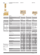
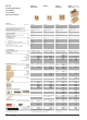
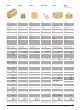
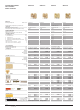
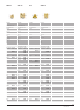
Technical data


1/124
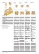
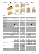
Earth test/disconnect terminals SAKT E/SAKA 10
Dimensions
Length mm
Height
(incl. TS32/TS35x7.5)
mm
Insulation stripping length mm
Connection data
Screw connection, solid
Screw connection, flexible
Conductor cross-section
VDE rated data
AC voltage
DC voltage
Current
Cross-section
Ordering data
Type
Cat.No. (6 mm
2
)
for TS 32 Y
Type
Cat.No. (6 mm
2
)
for TS 35 W
Type
Cat.No. (10 mm
2
)
for TS 32 Y
Type
Cat.No. (10 mm
2
)
for TS 32 Y/TS 35 W
Accessories
Mounting rail (2 m long)
End bracket (thickness 8.5 mm)
for TS 32 Y
for TS 35 W
SAKT E/SAKA 10
19/27
55/82
12
0.5…10 mm
2
/16 mm
2
0.5…6 mm
2
/10 mm
2
AWG 20…8
20…30 V~ 40…60 V~ 80…120 V~ 115 V~ 230 V~
10…15 V– 20…30 V– 40…60 V– 115 V– 230 V–
27 A 27 A/47 A 27 A 27 A/47 A 27 A/47 A
6 mm
2
6/10 mm
2
6 mm
2
6/10 mm
2
6/10 mm
2
SAKT E KrG SAKT E KrG SAKT E KrG SAKT E KrG SAKT E KrG
115872 069902 069922 069892 060682
SAKT E/35 KrG SAKT E/35 KrG SAKT E/35 KrG SAKT E/35 KrG SAKT E/35 KrG
116682 019792 019822 019802 019812
SAKA 10 SAKA 10
(24 V~) (only 230 V~)
117492 117502
SAKA 10 SAKA 10 SAKA 10
(24 V–) (115 V~) (230 V~)
815015 112882 810913
Type Cat.No. Qty.
TS 32 012280 –
TS 35 038340 –
EWK 1 020616 50
EW 35 038356 50
Earthing auxiliary circuits
“Earth vaults in control current circuits must not lead to
unintentionable start-up or dangerous movements of a machine,
or prevent shut-down of a machine. In order to fulfil this
requirement, one side of the control current circuits should be
connected to the protective conductor system and the coils and
switch elements should be correspondingly arranged.
For a control current circuit which is not connected to the
protective conductor system and supplied by a transformer, an
insulation monitoring unit must be included that reports an earth
fault and automatically switches of the circuit following an earth
fault.”
(VDE 01136.2.2)
Our earth test/disconnect terminals were specially designed for
use in control current circuits. They are designed so that reliable
and rapid disconnection from earth connection and an exact
display of the operating statuses are guaranteed. The mode of
operation makes a distinction between three different
conditions:
1. Operating mode
In operating mode, the control current circuit is solidly
connected to the earth connection via the closed side link. In
this way, a possible earth fault can be detected with the help of
a fuse and/or an r.c.c.b. because the leakage current can be
discharged to earth in the event of a fault.
2. Test mode
The test mode makes it possible to check the insulation
condition of the installation. The earth connection must be
disconnected for insulation measurements with voltages greater
than the rated voltage of the earth test/disconnect terminal.
3. Fault mode
If an earth fault occurs during operation in an earthed control
circuit , our earth test/disconnect terminals make it possible to
switch to a non-earthed control-circuit. This bridges the time
required to correct the fault, i.e. the machine can continue to
operate.
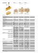
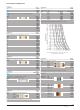
Modes of operation
Operating mode
SAKT E SAKA 10
– Side link closed
– Auxiliary current circuit earthed
– “Green” indicator illuminated
Test mode
For insulation measurements with voltages >U
rated,
the earth
connection must be disconnected.
SAKT E SAKA 10
– Side link open
– Auxiliary current circuit not earthed
– No earth fault
– “Green” and “red” indicators no indication
light up with reduced
intensity
– Earth connection disconnect
For insulation measurements with voltages >U
rated,
the earth
connection must be disconnect.
Operating mode
SAKT E SAKA 10
– Side link open
– Auxiliary current circuit not earthed
– Earth fault
– “Red” indicator illuminated