
Technical data


1/67
*Maintain the clearance and creepage when attaching wires. If necessary use a TW
Clearance and creepage table
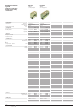
Terminals/accessoriesFeed-through terminals SAKG 28 I SAKG 28 II
Dimensions
Width/length/height (mm) With TS 32 Y
Width/length/height (mm) With TS 35 x 7.5 W
Insulation stripping length/Clamping screw/blade size
VDE rated data 0611 Part 1/8.92/IEC 947-7-1
Rated voltage/current/cross-section
Rated impulse voltage/pollution severity
Further technical data
Tightening torque range Nm
Torque setting with DMS2 electric screwdriver
Clampable conductors
“e” solid H07V-U mm
2
“m” stranded H07V-R mm
2
“f” flexible H07V-K mm
2
“f” flexible H07V-K and AEH DIN 46 228/1 mm
2
Gauge pin to 947-1 Size
Continuous current rating of cross-conn. 2…5-pole A
Continuous current rating of cross-conn. 6…10-pole A
UL/CSA rated data
Voltage/current/conductor size UL
Voltage/current/conductor size CSA
Ordering data Type
Melamine
End plate, hard paper (thickness mm)
for Y
Tropic proof
for W
Tropic proof
Partition. hard paper (thickness mm)
Tropic proof
Cross-connection
2-pole
3-pole
4-pole
Cover
Marking tags Print
Consecutive horizontal
Consecutive vertical
1 2 3 4 5 6
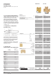
The Weidmüller SAKG range offers the
following connection variants:
• Clamping yoke connection, version III.
The stripped conductor can be
connected without further preparation.
• Lug connection, version II.
Two types of screw connection are
provided here:
a) Screw set with lock nut
b) with thread in busbar
• Clamping yoke/lug connection as a
combination, version I.
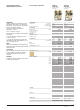
Versions
Version I Version II
without thread
Version II Version III
with thread
Cables with cable lugs are connected to
Version I SAKG terminals and SS stud
terminals.
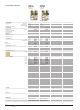
Fitting instructions for SAKG terminals
When tightening the clamping screw, it is
recommended that the conductor be held
against the tightening direction in order to
avoid any deformation of the mounting rail
and to keep the terminal foot free of
torsional forces.
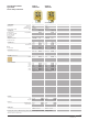
Cover
To ensure shock protection following
connection of the conductors, Type AH
hoods can be snapped onto the terminal.
28/70/63.5
–
15 mm/M 6/–
1000 V*/125 A/35 mm
2
8 kV/3
3…6
6…35
6…35
10…35
6…35
B 9
(QL 2) 110
600 V/95 A/2 AWG
600 V/110 A/6…1 AWG
Y Qty.
017002 10
Type Cat.No. Qty.
EP 1 (2) 020510 10
EP 1 (2) 020520 10
TW 1 (2) 015140 10
TW 1 016460 10
QL 2 019390 5
QL 3 040760 5
QL 4 040770 5
AH 28 032666 10
FW 5 047346 –
FS 5 047356 –
28/70/53
–
–/M 6/–
1000 V*/125 A/35 mm
2
8 kV/3
3…6
(QL 2) 110
600 V/115 A/2 AWG
600 V/110 A/6…1 AWG
Y Qty.
017032 10
Type Cat.No. Qty.
EP 1 (2) 020510 10
EP 1 (2) 020520 10
TW 1 (2) 015140 10
TW 1 016460 10
QL 2 019390 5
QL 3 040760 5
QL 4 040770 5
AH 28 032666 10
FW 5 047346 –
FS 5 047356 –
Mounting rails, brackets, additional marking material and accessories please see relevant Catalogue Section