
Technical data
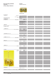


1/100
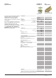
Slide-link disconnect
Types SAKT 1 and SAKT 4
is available in two designs.
Sliding link terminal.
Feed-through terminal.
The combinations of these designs enable the user to carry out
various connections. Plug bolts can be arranged in all designs
for test plugs.
Terminal 1
SAKT 1 as feed-through terminal with additional plug bolt.
Terminal 2
SAKT 1 as sliding link terminal with 2 plug bolts; slide link
closed.
Terminal 3 and 4
Slide link terminal connected by QVS, terminal 3; slide link open.
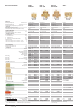
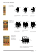
Slide-link disconnect
Types SAKT 2 has on each side of the disconnection, two
points for the testing plug or cross-connections. Cross-
connections can be made as fixed bridges or as cross-
connection links. These cross-connection links are especially
important for short-circuiting instrument transformers.
Terminal 1
SAKT 2 disconnect terminal with 4 plug bolts; disconnect
position closed.
Terminal 2, 3 and 4
SAKT 2 with QVS, terminal 2 and 3 connected, terminal 3 and 4
disconnected. Terminal 4 slide link connection open.
Terminal 5 to 8
SAKT 2 with QVS between terminals 5-6 and 7-8, both
disconnected; permanent cross-connection on terminals 6
and 8.
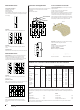
Typical test circuit applications
Voltage measurement with permanent meter on supply side and
meter plugged in on consumer side. Motor circuit is still
disconnected.
4 Terminals SAKT 043792.
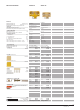
Cross-connection accessories
Cross-connection link QCS, 2, 3 and 4 ways to connect
adjacent terminals.
In SAKT 1 only to be used on the left hand side.
In SAKT 2 to be used on both sides.
Distance sleeves VH 19 031800 and screws BS 25.5 033470
are required to fit QVS in the individual terminals. The cross-
connection links are designed so that the plug bolts for test
plugs arranged in the terminals are kept free in each position.
The 2-pole design type QVS 2 is arranged also in such a way
that operating is possible when the plug bolts are fitted.
Plug bolts with insulation sleeve as protection for test plugs
and cross-connection plugs with 4.0mmØ.
Type StB 25
In SAKT 1 to be used for the left hand side.
In SAKT 2 to be used on both sides.
StB 25 black (027150)
BS 25 no insulating sleeve (033470)
BS (M3 x 25) 029250 BS (M3 x 25.5) 033470
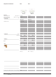
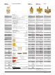
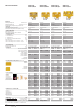
Additional cross-connection methods available for disconnect terminals
Part
Designation
QVS
Sleeve
Screw (M3 x25.5)
VL
Screw Bolt
Sleeve
Screw (M4 x 6)
Screw (M3 x 25)
Washer
Screw Bolt
Screw (M3 x 7)
Side Lock
Method of
Cross-connection
Side
Jumper Link
Connects
No. of ways
2
3
4
—
—
2
—
—
—
—
—
—
—
—
SAKA 10
—
—
—
—
—
VL2 013590
SB21 014700
—
BS 013630
—
SS 013640
—
—
—
SAKB 10
—
—
—
—
—
VL2 013590
—
—
BS 013630
—
SS 013640
—
—
—
SAKC 10
—
—
—
—
—
VL2 013590
—
—
BS 013630
—
SS 013640
—
—
—
SAKT 1
QVS2 030730
QVS3 032930
QVS4 030740
VH19 031800
BS 033470
VL2 013590
SB21 014700
VH19 028510
—
BS 029250
SS 016440
SB11 024270
BS 019970
SSP3 053176
SAKT 2
QVS2 030730
QVS3 032930
QVS4 030740
VH19 031800
BS 033470
—
—
—
—
—
—
—
—
SSP3 053176
TERMINAL BLOCK DESIGNATION
The creepage and clearance dimensions necessary for the nominal voltage of the terminals can be affected by the installation of
accessories. This is particularly so for cross-connections of adjacent terminals of different potentials. The following limitations are to
be observed.
SAKT 1 SAKT2
for adjacent QL 250V for adjacent QL 60V
for adjacent QVS 60V for adjacent QVS 60V
for adjacent StB 25 or StB 16 60V for adjacent StB 25 or StB 16 60V
In order to retain the nominal voltage of 300V, Partitions TW or TSch 2 must be inserted. TSch 2 only to be used for SAKT 2.
Please refer to the accessories Section.
1
2 3 4 QVS 2
2 3 41
5 6 7 8
1 2 3 4
M
V
V
Test Voltmeter
Motor
Voltmeter
1
A
QVS 2S
QVS