IDE 4000 Flash Disk 1.8" and 2.5" Product Specification and User Manual January 2005 34-PS-0304-00 Rev. 2.
DOCUMENT CONTROL INFORMATION DCO No.: Title Issued by: Name VP Marketing, Embedded Division Ofer Tsur Date January 5, 2005 REVISION HISTORY Revision Date 2.0 June 7, 2004 2.1 Description Added information for new 1.8” form factor January 2, 2004 -- Updated available capacity information Section 1.2.8 Updated reliability information Section 1.2.
TABLE OF CONTENTS 1. Specifications........................................................................................................................ 5 1.1. Critical Item Definition .................................................................................................... 5 1.2. Characteristics................................................................................................................ 5 1.2.1. Interface Definition..........................................................
8. Warranty............................................................................................................................... 21 9. Ordering Information .......................................................................................................... 22 How to Contact Us .................................................................................................................... 23 4 Product Specification and User Manual IDE 4000 Flash Disk 34-PS-0304-00 Rev. 2.
1. SPECIFICATIONS 1.1. Critical Item Definition The dimensions of the IDE 4000 flash disk enable mounting in a standard 2.5”or 1.8” disk drive bay, as described in Section 1.2.11. Note: The information written in this document refers to both IDE 4000 2.5” and 1.8” unless otherwise stated. 1.2. Characteristics 1.2.1. Interface Definition The IDE 4000 supports the commands listed in Section 4, in compliance with ATA4 standards. 1.2.2.
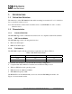
Figure 1: IDE 4000 Performance Results 1.2.4. Access Time Standby to active (typical.): 0.1 msec 1.2.5. Seek Time The IDE 4000 has no seek time, as it has no moving parts. 1.2.6. Input Voltage The IDE 4000 input voltage is 3.3VDC to 5.0VDC. 1.2.7. Current Consumption The current consumption at an input voltage of +5 VDC is described in Table 2. Table 2: IDE 4000 Input Current Consumption with +5 VDC Input Voltage 6 Function/Mode Current (max) mA DC Read 23.0 Write 23.0 Idle/Sleep 5.
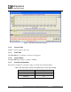
The current consumption at an input voltage of +3.3 VDC is described in Table 3. Table 3: IDE 4000 Input Current Consumption with +3.3VDC Input Voltage 1.2.8. Function/Mode Current (max) mA DC Read 16.0 Write 16.0 Idle/Sleep <1 Memory Capacity As of software version 1.09, the changes listed in Table 4 apply to the CHS (Cylinder, Heads, Sectors) settings for the IDE 4000, capacities 128MB to 512MB (there are no changes for other capacities).
1.2.9. Endurance The IDE 4000 provides 2,000,000 write/erase cycles and an unlimited number of read cycles. Performance is enhanced by the following features: • Wear-Leveling Algorithm: This algorithm guarantees the use of all flash components at the same level of the write/erase cycle. • EDC/ECC (Error Detection Code/Error Correction): The enhanced Reed-Solomon EDC/ECC extends disk endurance by detecting and then fixing flash blocks. 1.2.10.
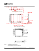
Recommended Tightening Tourqe is 6.0 in-lb (0.675 N-m) Recommended Tightening Tourqe is 6.0 in-lb (0.675 N-m) Figure 2: IDE 4000 2.5” Assembly Figure 3: IDE 4000 1.8” Assembly Notes: 1. All dimensions are in mm [in]. 2. General tolerance is ±0.25 mm [±0.01 in]. 9 Product Specification and User Manual IDE 4000 Flash Disk 34-PS-0304-00 Rev. 2.
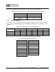
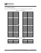
1.2.11.3 Connector Interface The pinout for the IDE 4000 interface connector is detailed in Table 9 and in Figure 4. Table 9: J1 Pin Assignment Pin Number Signal Name Pin Number Signal Name 1 RESET- 2 GND 3 HD7 4 HD8 5 HD6 6 HD9 7 HD5 8 HD10 9 HD4 10 HD11 11 HD3 12 HD12 13 HD2 14 HD13 15 HD1 16 HD14 17 HD0 18 HD15 19 GND 20 KEY 21 N.C. 22 GND 23 HIOW- 24 GND 25 HIOR- 26 GND 27 IORDY 28 CSEL 29 N.C.
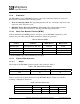
Figure 4: IDE 4000 Pin Configuration 1.3. Environmental Conditions The IDE 4000 meets the performance requirements specified below, after exposure to non-operating environmental conditions, or during and after exposure to operating environmental conditions. 1.3.1. Temperature 1.3.1.1 Operating The IDE 4000 operates without degradation at a pressure of 1 atm over the following ambient temperature range: • Commercial temperature version: 0°C to +70°C : for IDE 4000 2.5” and 1.
1.3.1.3 Airflow Requirements General airflow guideline: 3-5 cu.feet/min. 1.3.2. Altitude The IDE 4000 sustains full operation at altitudes ranging from sea level to 80,000 feet above sea level. It is also capable of full operation during air transportation via non-pressurized flights at altitudes greater than 80,000 feet above sea level. 1.3.3. Relative Humidity The IDE 4000 withstands conditions of 8% to 95% non-condensing relative humidity (operation and non-operation). 1.3.4.
2. DRIVE CONFIGURATION The IDE 4000 must be configured as shown in Figure 5 before being mounted in the system’s drive bay. Figure 5: IDE 4000 Disk Address Setting by Jumper 13 Product Specification and User Manual IDE 4000 Flash Disk 34-PS-0304-00 Rev. 2.
3. INTERFACE CONNECTORS The IDE 4000 has a 2-mm pitch interface connector located on the rear panel. It accesses the DC power source and the IDE bus through a non-shielded 44-pin flat cable. Figure 6 provides an example of a connector that can be used to interface with this connector, but any compatible connectors may be used.
4. SUPPORTED IDE COMMANDS The IDE 4000 supports the commands listed in Table 11.
5. CE AND FCC COMPATIBILITY The IDE 4000 complies with the following CE requirements and FCC standards: • FCC Part 15 Class B • EN 55022 Class B, CISPR 22 Class B (MIC) • V-3/2001.04 Class B (Japan), AS/NZS 3548 Class B (Australia/NZ) • BSMI CNS 13438 Class B (Taiwan) • CAN/CSA-CISPR 22-96 Class B (Canada) CFR 47 FCC Class B • EN 55024, EN 61000 (EMC) 16 Product Specification and User Manual IDE 4000 Flash Disk 34-PS-0304-00 Rev. 2.
6. LABEL INFORMATION The outside label contains the following information: 5 6 7 8 1 2 3 4 9 Figure 7: Outside Label 1. CE and FCC logos 2. Product name 3. Unformatted capacity value 4. M-Systems logo 5. Ordering information 6. Serial number, including date code 7. Part number 8. Declaration 9. ESD warning logo and statement 17 Product Specification and User Manual IDE 4000 Flash Disk 34-PS-0304-00 Rev. 2.
7. USING THE IDE 4000 FLASH DISK The IDE 4000 is shipped with the following components: • Warranty certificate indicating M-Systems’ 36-month warranty • Four screws and one jumper, in kit no. 48-PK-001-00 If any of these items is missing, please contact your dealer. 7.1. Unpacking the Drive Before unpacking or handling a drive, take all proper electrostatic discharge (ESD) precautions, including personnel and equipment grounding.
3. Connect a 44-pin ribbon cable between the IDE 4000 and the adapter. Make sure to orient the cable so that pin 1 of the IDE 4000 is connected to pin 1 of the host adapter. 4. Mount the IDE 4000 in a free drive bay. 5. Close the PC cover and power on the PC. The host BIOS sign-on message appears and displays a key sequence to enter the BIOS setup. Set up the BIOS to recognize the IDE 4000. 7.4.
7.6. How to Get Help If you need technical assistance with the installation and configuration of your IDE 4000, please contact your customer support representative and have the following information available: • Product and serial number of your IDE 4000 • Description of your computer hardware (manufacturer, model, attached devices, etc.) • Description of your IDE host adapter and associated drivers • Description of your software (operating system, version, application software, etc.
8. WARRANTY The warranty period of the IDE 4000 is 36 months (3 years). For details, please refer to the warranty certificate, which is included with the IDE 4000. 21 Product Specification and User Manual IDE 4000 Flash Disk 34-PS-0304-00 Rev. 2.
9. ORDERING INFORMATION Ordering information for the IDE 4000 2.5”: IDE-4K-25-CCCC-T Ordering information for the IDE 4000 1.8”: IDE-4K-18-CCCC-T Where: CCCC: Capacity (MB) 128, 256, 384, 512, 640, 768, 1024, 1280, 1536, 1792, 2048, 2560, 3072, 3584, 4096, 5120, 6144, 7168, 8192 T: Temperature Range Blank Commercial: 0°C to +70°C (for 2.5” and 1.8”) X Extended: -40°C to +85°C (for 2.5” only) Note: the IDE 4000 in a 1.8” casing is available only in commercial temperature range.
HOW TO CONTACT US USA China M-Systems Inc. 555 North Mathilda Avenue, Suite 220 Sunnyvale, CA 94085 Phone: +1-408-470-4440 Fax: +1-408-470-4470 M-Systems China Ltd. Room 121-122 Bldg. 2, International Commerce & Exhibition Ctr. Hong Hua Rd. Futian Free Trade Zone Shenzhen, China Phone: +86-755-8348-5218 Fax: +86-755-8348-5418 Japan Europe M-Systems Japan Inc. Asahi Seimei Gotanda Bldg., 3F 5-25-16 Higashi-Gotanda Shinagawa-ku Tokyo, 141-0022 Phone: +81-3-5423-8101 Fax: +81-3-5423-8102 M-Systems Ltd.