
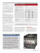
Specifications

52 May 2013 ARRL, the national association for Amateur Radio
®
www.arrl.org
Front Panel
The straightforward front panel has all of the
information needed to operate the amplifier
except a wattmeter to show power output. The
ON/OFF switch controls the integrated ac power
supply, and the POWER switch places the am-
plifier inline or bypasses it as needed. The JT
MODE switch moves the amplifier into more
efficient class C operation to run con-
tinuous modes such as WSJT and FM
that do not require linear operation.
Amplifier output is slightly reduced
when it is in JT MODE (see Table 2).
The
+50V
LED indicates that power is
on, and
READY
lights if the amplifier is
inline. There is also a
VSWR/TEMP
LED to indicate high SWR or ampli-
fier overheating. The
JT
LED shows that the amp
is in JT mode, and the
TX
indicator shows that the amplifier
has been keyed and is in transmit
mode.
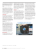
Rear Panel Connections
The rear panel (Figure 5) includes jacks for
the input from the transceiver and the output to
the antenna. Neither jack is marked, though
they are clearly shown in the instructions. This
is not a major issue, but labels would be nice
(and easy to add), especially for those who
take the amplifier to a portable location and
need to break down the station from time to
time. Internally there is an RF coaxial relay on
the input side and a high power vacuum relay
on the output. No additional relays should be
needed, a nice feature for added simplicity of
operation.
The rest of the rear panel includes the phono
jack to key the amp, as well as a terminal strip
with a 13.6 V at 500 mA output and a switch-
ing contact that could be useful for external
relays and preamps. Early versions of the am-
plifier had a 20 pin connector used for factory
testing only. This connection has been moved
inside on later versions. Other than the chassis
ground, I did not need to use any of these con-
nection points.
Using the Amplier
After years of using tube type amplifiers re-
quiring high voltage supplies and warm up pe-
riods, I found that operating the 2M-1K2 is
about as simple and quick as it can get. After
pushing the
ON
and
POWER
buttons, the am-
plifier is ready to go. That is a nice feature of
solid state amplifiers and it made me think of
all the times over the years that I have run into
Reviewed by Jeff Klein, K1TEO
QST Contributing Editor
wa2teo@aol.com
You can have a lot of fun on 2 meters with
the 50 or 100 W available from a modern
transceiver or transverter. That’s plenty of
power for local contacts and for DX when
the band is open, but you’ll eventually want
more power if you start to get serious
about working VHF contests, DX or
some of the more challenging propaga-
tion modes such as scatter or EME
(moonbounce).
VHF operators have a number of
choices for power amplifiers up to the
legal limit of 1500 W. Solid state
“brick” amplifiers typically provide
power up to about 300 to 400 W.
Beyond that power level, tube type am-
plifiers have traditionally been required.
High power solid state amplifiers are
now practical with a new generation of
MOSFET devices that run at higher
voltage levels (about 50 V) instead of
12 or 28 V. This creates some interest-
ing new choices.
Enter M
2
, long known for a wide
selection of antennas and accessories.
M
2
has expanded into the solid state
power amplifier arena as well with high power
amplifiers for 6 and 2 meters. Both models are
compact and light weight, offering substantial
power in a package that fits comfortably in any
home shack or portable station. This review
takes a look at the 2M-1K2 for 2 meters, ca-
pable of running 1250 W output on SSB or
CW and about 900 W on continuous modes
such as FM voice or digital modes that you
can operate using WSJT.
Options
The 2M-1K2 allows the option of using an in-
tegrated power supply from M
2
or supplying
your own (48-50 V at 40-50 A). The review
unit included the M
2
supply. One of the goals
M
2
set for this amplifier was to make it small
and lightweight. With the power supply, the
package measures 7
1
⁄4 × 15 × 14 inches
(HWD) and weighs just over 20 pounds —
small and lightweight indeed.
Setup
The M
2
amplifier package is ready to go and
reminiscent of adding a linear amplifier to an
HF station. Setup involved only a few steps,
starting with a 240 V ac line for the power
supply. It came with an ac power cord that I
then mated with a plug to match the existing
M
2
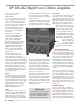
2M-1K2 High Power 2 Meter Amplifier
Bottom Line
The M
2
2M-1K2 is a quiet and conve-
nient solution for high power operation
on 2 meters. It puts out near legal limit
power and is compatible with most
modern transceivers or transverters.
240 V wall socket in my shack. If the optional
M
2
power supply is not used, the amplifier
comes with #10 AWG leads for connecting an
external dc supply.
The 2M-1K2 has a built-in TR relay (ground
to transmit), connected through a phono jack
on the back panel. My station uses a TR se-
quencer that is operated with a footswitch. The
TR sequencer makes sure that my transceiver,
amplifier and preamplifier are all keyed in the
correct order, with no “hot switching” of re-
lays. Hooking up a connection between the se-
quencer and the amplifier for keying was
straightforward. A direct connection between
the transceiver and the amplifier can also be
used, but for reasons discussed later it is ad-
vantageous to use a sequencer.
The rear panel has Type N female connectors
for RF input and output. Be sure that you’re
using coaxial cable rated to handle 1200 W on
2 meters. The manual recommends using a
wattmeter between the amplifier and antenna
as no internal wattmeter or SWR meter is in-
cluded. Once these connections are made the
amplifier is ready to go.