
Technical information
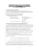
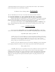
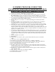
Table Of Contents
46
• use oxide-sharpened Si
3
N
4
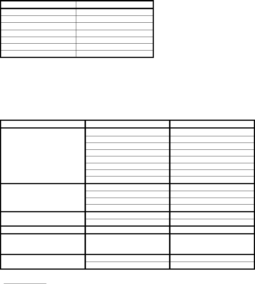
probe tips, e.g. Model NPS which has the following specifications
(http://www.di).com/products2/NewProbeGuide/ContactModeProbes.html :
PARAMETER VALUE
spring constant 0.58 N/m
nominal tip radius of curvature 5-40nm
cantilever leg length
100µm
cantilever configuration V-shaped
reflective coating Au
shape of tip square pyramidal
tip half angle 35
o
• use piezo scanner with smallest distance range available, A or EV scanner, E scanner should also work (the
difference is the engagement mechanism).
• load sample, turn microscope and vibration table on, and then focus the laser as far out on the cantilever as
possible to obtain the highest sensitivity
• let the system stabilize thermally for 30 minutes (with hood on)
• laser focusing (find maximum): the laser should never been switched off, i.e. turn the system on and off and
all manipulations done with the laser on
PANEL PARAMETER SETTING
Scan size
1 µm
X offset 0.00 nm
Y offset 0.00 nm
Scan angle 0.00 deg
Scan rate 61.00 Hz
Number of samples 512
Slow scan axis enabled
Scan Controls
Z limit between 55V-440V
Integral gain 0.001
Proportional gain 0.00
Lookahead gain 0.00
Feedback Controls
Setpoint 0 V
AFM mode Contact Other Controls
Input attenuation 1x
Interleave Controls Interleave mode Disabled
Channel 1 Data type Height*
(*setting this parameter to
deflection is typically easier)
Highpass filter OFF, 3-4
Lowpass filter OFF, 1
III. Imaging
• Engage the surface. Make sure you are not false engaged (*see Section 10.10.1 of the DI AFM Manual).
• Reduce
Scan Size
to ~12 nm.
OR
• Engage with the Scan Size set to zero and slowly increase.
• Increase Scan Rate to 60Hz. Notice that if the Scan Rate is set much higher for atomic scale images to
defeat some of the noise due to thermal drift.
• Adjust Integral Gain, Setpoint, Scan Rate, and Scan Angle to obtain a good image. Initially, the Setpoint
should be kept as low as possible initially and then increased to obtain an image. The Z-center position
should be close to 0V. The Scan Angle is known to have a huge effect, with optimal imaging conditions if the