
Technical information
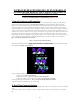
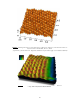
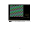
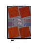
Table Of Contents
51
IV. Off-line Image Analysis.
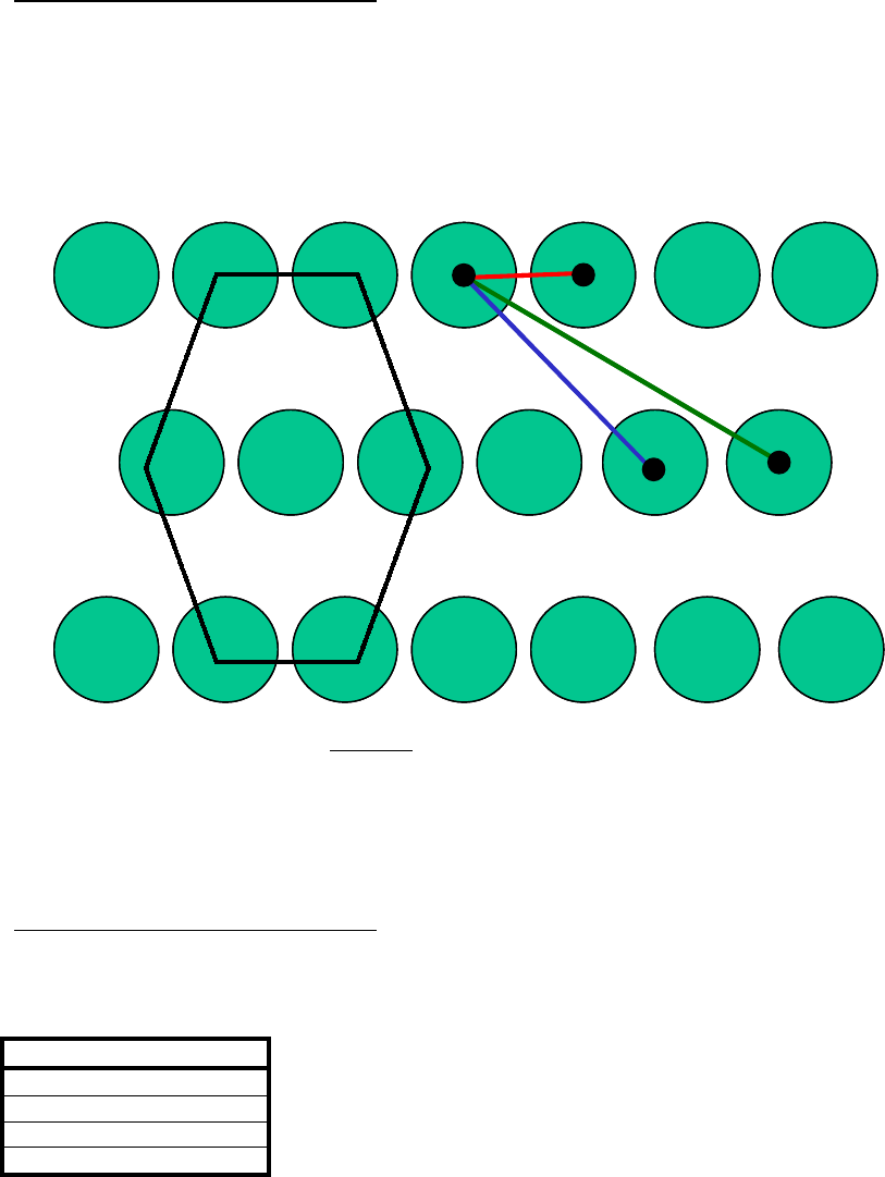
• Go to Off-line / View / Top View option and measure the spacings between atoms. The spacings should
be as follows (as shown in Figure 5) :
MICA : A=0.519 nm, B=0.900 nm, C=1.37 nm
HOPG : A=0.255 nm, B=0.433 nm, C=0.666 nm
Figure 5.
Hexagonal Atomic Lattice
Record the spacings for ~ 10 atoms observed in a captured image and average them. This can be done by
alternatively "walking" the cursor line from atom to atom; the average distance will be shown on the bottom
right hand corner of the display monitor's status bar. If the measurements vary by more than 2 percent from
the dimensions shown above, a correction should be made as follows.
V. X and Y Axis Corrections
• See Sections 15-7.2-15-7.3 of the DI Multimode manual. The only difference is that the known distances
must be adjusted for the smaller atomic spacings of the atoms. Furthermore, the sensitivity parameters are
adjusted for atomic-scale imaging as follows :
PARAMETER
X fast sens 0
o
Scan Angle
X slow sens 0
o
Scan Angle
Y fast sens 90
o
Scan Angle
Y slow sens 90
o
Scan Angle
The derate parameters are not changed for atomic scale imaging including ; x fast derate, x slow derate, Y fast
derate, Y slow derate, retracted offset der, extended offset der.
As stated in section 15-7.9 in the DI Multimode manual, the sensitivity parameters must be calibrated with the
Scan angle set at both 0 degrees and 90 degrees. Z-axis calibration is done the normal way using a silicon
calibration reference (see Section 15.8 of the Multimode Manual for detailed instructions).
A
B
C
hexagonal atomic lattice
A
B
C
hexagonal atomic lattice