installation instructions Guide d’installation ALCOVE SHOWER INSTALLATION (3 WALLS) INSTALLATION DOUCHE EN ALCÔVE (3 MURS) HARDWARE INCLUDED IN BOXES View Installation Video - Scan QR code with a mobile device QUINCAILLERIE INCLUSE DANS LES BOÎTES OPEN ALL BOXES BEFORE YOU START OUVREZ TOUTES LES BOÎTES AVANT DE COMMENCER Voir Vidéo d'installation - Balayer QR code avec un dispositif mobile A two person installation is required. Une installation par deux personnes est requise.
For installation steps in ENGLISH go to page 6 Table of contents: Page Tools and supplies.............................................................................................................. 3 Parts and components........................................................................................................ 5 1. Building the structure..................................................................................................... 6 2. Installing the base.......................
TOOLS OUTILS REQUIRED REQUIS 1/8" drill bits Mèches de 1/8 24" level min. Niveau de 24po. min. Hole saw Scie-cloche Utility knife Couteau à lame rétractable Pencil Crayon Electric drill Perçeuse électrique Safety equipment Équipement de sécurité Screwdriver Tournevis Measuring tape Ruban à mesurer 18" square min. Équerre de 18po. min.
PARTS PIÈCES Inside the sidewall box À l'intérieur de la boîte du mur de côté PARTS INCLUDED IN PARTS PACK | PIÈCES COMPRISES DANS L'EMBALLAGE DES PIÈCES 1 n -1 for junctio ar Utile MA n AX -1 for by/p pack VISTA junctio ar 303 1 IEURE E VIEW IOR INSIDINTÉR VUE INTER VISTA 1 3 3 ge daño brisa o damaou or perdid lossde perte de caso 4 IEURE E VIEW IOR INSIDINTÉR VUE INTER VISTA Part Nom de la pièce Qty/Qté 1 X fastener Fixation en forme de X 4 2 #8 x 1¼’’ Screw (for X fastene
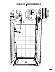
Overview Vue d'ensemble 15 2 9 8 6 1 4 3 14 10 7 INSIDE VIEW VUE INTÉRIEURE 5 15 14 15 13 5
For a worry free installation follow all instructions and check them off as you go. 1 STEP Building the structure Before starting make sure to have all parts and components refer to page 4. Build a structure based on the dimensions in the chart below. No. Olympia square 4832 106011 Olympia square 6032 106012 A B Between 48"- 48 1/4" Between 60"- 60 1/4" 33 1/2" min. 33 1/2" min.
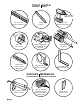
2 STEP Installing the base Remove clear plastic film on the base. Use cardboard on the base floor as protection until the installation is complete. 2.1 Check me! Top view Rubber Cardboard Apply a 1/8" width silicone bead around the edge of the drain hole in the base (refer to illustrations). Assemble as shown. Hand tighten only ! VERIFY THE MAAX LOGO ON THE DRAIN COVER IS FACING THE RIGHT WAY REMOVE EXCESS SILICONE! Threshold 2.
2 STEP Installing the base (cont'd) If needed use wood shims between the studs and the fastening flange to maintain centered position of base. 2.4 Check me! Do not use shims UNDER THE BASE to leveL! doing so will void the Maax warranty! 13 With a 1/8" bit, drill holes in the fastening flange then secure the base to all the wall studs with #8 x 1¾ " screws (not included). Only pre-drill the flange not the studs. 2.
STEP 3 Installing Ulok system on the walls junctio ar Utile -1 MAA for by/p 1 – ULOK X n X n -1 for pack Skin 03 VISTA junctio ar Utile 03 1 – ULOK VISTA 2 WALL E BACK IOR ARRIÈR MUR POSTER MURO 3 1 1 WALL CÔTÉ L SIDE DE MUR LATERA MURO WALL CÔTÉ L SIDE DE MUR LATERA MURO 4 4 3 3 e daño brisa o damag ou or perdid loss perte de of de case cas caso in s enue en pack incluse empaq this in sont ed ires en este as includ menta are incluid parts supplé están 4 2 VIEW EURE O
STEP 4 Temporary installation of the back wall 4.1 Check me! Pull back the protective film on the walls (14-15) at least 3" away from all edges. Keep the remaining protective film on the walls. 14 4.2 Check me! Position and level the back wall (14) by sitting it on the threshold at the back of the base. Plumbing the back wall is critical for alignment of the side walls Back wall Quick tip Installing the walls temporarily will ensure proper wall alignment before permanent installation.
STEP 5 Temporary installation of the side walls 3 Install the side wall (15) on the opposite side of the faucet installation. Lift the wall approximately 3" above the threshold of the base, push it completely against the back wall then lower the side wall into position. 5.1 Check me! 1 Back wall 15 It is critical that all 3 retraction pins engage with the X fasteners. There should be no gap between the walls. Quick tip Quick tip The side wall should now line up with the front of the base.
STEP 5 Back wall Temporary installation of the side walls (Cont'd) Measure the distance between the front face of the back wall (14) and the center of the faucet. Then measure the distance from the top of the base threshold to the center of the faucet. Top view 5.3 Check me! Faucet center Using those two measurements mark the position of the faucet hole on the remaining side wall. Measure from the side and bottom of the side wall where the retraction pins are installed.
STEP 5 3 Temporary installation of the side walls (Cont'd) Side wall Install the side wall (15) with the drilled faucet hole(s). Lift the wall approximately 3" above the threshold of the base, push it completely against the back wall then lower the side wall into position. 5.6 Check me! Make sure the retraction pins are properly inserted in the X fasteners. There should be no gap between the walls. Quick tip Quick tip The side wall should now line up with the front of the base.
STEP 6 Final installation of back wall Remove all walls from the structure. Clean the shower base and apply a bead of silicone on the threshold at 3/8" from the back fastening flange. Run the bead of silicone the entire length of the base and 1'' on each side also. 6.1 Check me! 6.2 Check me! ⅜" 1" ⅜" 13 Lift and place back wall (14) directly over the silicone without sliding. Verify that the back wall (14) is plumb, shim if needed.
STEP 7 Final installation of side walls 3 Install the side wall (15) opposite the faucet. Lift the wall approximately 3 inches above the threshold of the base, push it completely against the back wall then slide the side wall into position. 7.1 Check me! Side wall 1 WIPE OFF EXCESS SILICONE Back wall Install the side wall (15) with the faucet hole. Lift the wall approximately 3 inches above the threshold of the base, push it completely against the back wall then slide the side wall into position.
STEP 7 Final installation of side walls (cont'd) Check me! Secure the walls to the wall studs with #8 x 1¾ " screws (not included) in the previously drilled holes. Also, secure the walls by the fastening flanges on the sides of the walls. Use the pre-dilled holes. If needed, use shims to keep walls plumb, square and leveled. (Cut shim excess) IMPORTANT: Hand tighten only. DO NOT OVER-TIGHTEN THE SCREWS.
STEP 9 Silicone Apply a bead of silicone all along the wall to wall and wall to base joints. For a smooth finish you can remove the silicone excess with a damp rag or wet finger. Quick tip Check me! Remove protective film from walls Apply masking tape on both sides of the joint where you will run a bead of silicone. Apply the silicone, smooth with a wet finger then remove the masking tape. All faucets installed on the walls must be sealed with silicone. 10 STEP Glass shelf installation 10.
10 STEP Glass shelf installation (cont'd) 10.2 Check me! Clean the top rubber part of the brackets with a damp cloth, then place the glass shelf (5) over the brackets (6). Quick tip 5 If you can read the MAAX logo, the shelf is installed on the right side. 6 6 10.3 Check me! Insert the washers (8) in the shelf support cap (9). Align and insert the shelf support caps (9) with the holes of the glass and the holes of the shelf brackets (6).
Pour une installation sans tracas suivre les étapes une à une et les cocher lorsqu’elles sont terminées. 1 ÉTAPE Construction de la structure Avant de commencer assurez-vous d'avoir tout les pièces et composantes se référer à la page 4. Construire une structure qui respecte les dimensions mentionnées dans le tableau. C Si la structure est existante, s'assurer que ses dimensions correspondent à celles du tableau.
ÉTAPE 2 Installation de la base Retirer la pellicule transparente sur la base. Utiliser du carton dans le fond de la base comme protection jusqu'à la fin de l'installation. 2.1 Cochez-moi! Rondelle de caoutchouc Vue de dessus Rondelle de carton Appliquer de la silicone autour du trou du drain de la base (réferez-vous aux illustrations). Assembler le drain tel qu'illustré. SERRER À LA MAIN SEULEMENT! S'ASSURER QUE LE LOGO MAAX SUR LE COUVERT DU DRAIN FAIT FACE À L’AVANT DE LA BASE.
ÉTAPE 2 Installation de la base (suite) Au besoin, utiliser des cales de bois entre la base et les montants pour maintenir la base en position centrée. 2.4 Cochez-moi! NE PAS UTILISER DES CALES DE BOIS SOUS LA BASE POUR LA METTRE DE NIVEAU; CELA ANNULERA LA GARANTIE! Percer des avant-trous dans la bride de la base seulement, avec une mèche de 1/8 po. Ne pas percer les montants. Fixer la base à tous les montants à l'aide de vis #8 x 1–¾ po (non incluses). 13 2.
ÉTAPE 3 Installation du système Ulok sur les murs junctio ar Utile -1 MAA for by/p 1 – ULOK VISTA junctio ar Utile 03 1 – ULOK VISTA 2 WALL E BACK IOR ARRIÈR MUR POSTER MURO 3 1 1 WALL CÔTÉ L SIDE DE MUR LATERA MURO WALL CÔTÉ L SIDE DE MUR LATERA MURO 4 4 3 3 e daño brisa o damag ou or perdid loss perte de of de case cas caso in s enue en pack incluse empaq this in sont ed ires en este as includ menta are incluid parts supplé están 4 2 VIEW EURE OR INSIDE INTÉRI VUE INTE
ÉTAPE 4 Installation temporaire du mur arrière Retirer au moins 3 ou 4 po de pellicule transparente de tous les côtés du mur arrière. Laisser le reste de la pellicule collée sur le mur. Positionner le mur arrière (14) en le déposant sur le seuil arrière de la base, puis le mettre de niveau. 4.1 Cochez-moi! 14 4.2 Cochez-moi! Il est essentiel de mettre le mur arrière de niveau pour assurer l’alignement des murs de côté.
ÉTAPE 5 Installation temporaire des murs de côté 3 Installer d’abord le mur de côté (15) du côté opposé à la robinetterie. Placer le mur à environ 3 po au-dessus du seuil de la base, le pousser à fond contre le mur arrière, puis l’abaisser sur le seuil de la base. 5.1 Cochez-moi! 1 Mur de côté Mur arrière 15 Il est essentiel que les chevilles d'ancrage soient bien insérées dans les fixations en X. Il ne devrait y avoir aucun espacement entre le mur de côté et le mur arrière.
ÉTAPE 5 Mur arrière Installation temporaire des murs de côté (suite) Mesurer la distance entre la face du mur arrière et le centre de la robinetterie. Mesurer ensuite la distance entre le seuil de la base et le centre de la robinetterie. Vue de dessus 5.3 Cochez-moi! Centre de la valve Reporter les mesures de la position du trou de la robinetterie sur le mur de côté non installé. Mesurer à partir du bas du mur et du côté des chevilles d'ancrage.
ÉTAPE 5 3 Installation temporaire des murs de côté (suite) Mur de côté 5.6 Cochez-moi! Installer le mur de côté (15) une fois le/les trou(s) de robinetterie percé(s). Placer le mur à environ 3 po au-dessus du seuil de la base, le pousser à fond contre le mur arrière, puis l’abaisser sur le seuil de la base. Il est essentiel que les chevilles d'ancrage soient bien insérées dans les fixations en X. Il ne devrait y avoir aucun espacement entre le mur de côté et le mur arrière.
ÉTAPE 6 Installation finale du mur arrière Retirer tous les murs de la structure. Nettoyer la base et appliquer un trait de silicone sur le seuil de la base à 3/8 po de la bride arrière. Appliquer de la silicone sur toute la longueur arrière ainsi que sur 1 po de chaque côté. 6.1 Cochez-moi! 6.2 Cochez-moi! ⅜" 1" ⅜" 13 Soulever et mettre en place le mur arrière (sans le glisser) directement sur la silicone. S'assurer que le mur arrière (14) est de niveau, ajouter des cales de bois au besoin.
ÉTAPE 7 Installation finale des murs de côté 3 Installer le mur de côté (15) opposé à celui de la robinetterie. Placer le mur à environ 3 po au-dessus du seuil de la base, le pousser à fond contre le mur arrière, puis l’abaisser sur le seuil de la base. 7.1 Cochez-moi! Mur de côté 1 Mur arrière ENLEVER L’EXCÉDANT DE SILICONE. Installer le mur de côté (15) doté de trou(s) de robinetterie.
ÉTAPE 7 Installation finale des murs de côté (cont'd) 7.4 Cochez-moi! Fixer les murs arrière et les murs de côté à tous les montants à l'aide de vis #8 x 1–¾ po (non incluses). Visser les murs de côté en utilisant les avant-trous de la bride. Au besoin, utiliser des cales de bois pour assurer que les murs sont de niveau et verticaux. (Couper l'excédant des cales) IMPORTANT : SERRER À LA MAIN UNIQUEMENT. NE PAS TROP SERRER LES VIS.
ÉTAPE 9 Silicone Enlever la pellicule protectrice des murs Appliquer un trait de silicone sur toute la longueur des joints (mur à mur et mur à base). Pour une belle finition, enlever l'excédant de silicone avec un chiffon humide ou un doigt mouillé. Conseil éclair Cochez-moi! Appliquer du ruban-cache de chaque côté du joint où le trait de silicone sera appliqué. Appliquer la silicone, lisser avec un doigt mouillé, puis enlever le ruban-cache.
10 ÉTAPE Installation de la tablette (suite) 10.2 Cochez-moi! Nettoyer la partie en caoutchouc sur le dessus des supports avec un chiffon humide. Placer ensuite la tablette (5) sur les supports (6). Conseil éclair 5 La tablette est sur le bon côté s’il est possible de lire le logo MAAX. 6 6 10.3 Cochez-moi! Insérer les bouchons (9) dans les rondelles (8). Aligner les trous de la tablette et ceux des supports (6), puis y insérer l’assemblage du bouchon (9).
LIMITED WARRANTY Garantie limitée MAAX Bath Inc. (hereafter “MAAX”) offers an express limited warranty on each of its products. This warranty extends only to the original owner/end-user for personal household use. For commercial uses, additional limitations apply. MAAX Bath Inc. (ci-après “MAAX”) offre une garantie limitée expresse sur chacun de ses produits. Cette garantie s’adresse uniquement au propriétaire/utilisateur original pour un usage personnel domestique.
TECHNICAL DRAWINGS
U tile Shower Unit Shower 48" x 32" BACK WALL SIDE WALL 32 1/2" 47 5/8" 1 1/8" 7/8" 7/8" 80 7/8" 3/8" 80 7/8" 7/8" TOP VIEW (ASSEMBLED) 45 1/2" This product is designed to be installed in a building that conforms with the requirements of the National Building Code of Canada 2005 All dimensions are approximate. Structure measurements must be verified against the unit to ensure proper fit.
U tile Shower Unit Shower 60" x 32" BACK WALL SIDE WALL 59 5/8" 3/8" 1 1/8" 32 1/2" 7/8" 7/8" 80 7/8" 80 7/8" 7/8" TOP VIEW (ASSEMBLED) 57 1/2" This product is designed to be installed in a building that conforms with the requirements of the National Building Code of Canada 2005 All dimensions are approximate. Structure measurements must be verified against the unit to ensure proper fit.
U tile Tub Shower Kit Tub Shower 60" x 30" BACK WALL SIDE WALL 59 3/4" 7/8" 3/8" 7/8" 1 1/8" 60 7/8" 60 7/8" TOP VIEW (ASSEMBLED) 59 7/8" 57 5/8" 28 3/4" This product is designed to be installed in a building that conforms with the requirements of the National Building Code of Canada 2005 All dimensions are approximate. Structure measurements must be verified against the unit to ensure proper fit.