
Installation Instructions
24
A
B
C
D
14”(356mm) NOT ABFLR
16”(406mm) ABFLR (standard)
Recessed 3/8”
Encastré 3/8”
Empotrado 3/8”
(9.5mm)
B
For unit with massage system
Pour les unites avec système de massage
Para unidades con sistema de masaje
Top view
Vue superieure
Vista superior
3/8”
Wall
Mur
Muro
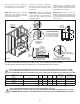
For flush finish installation
Pour une installation d’équerre
Para una instalación rasante
23½
”
3/8”
B
19”
51½”
Side view
Vue de côté
Vista lateral
19” h (483mm) if AFR (standard)
17” h (432mm) if not AFR
19” h(483mm) si AFR (standard)
17” h (432mm) si ne pas AFR
19” h (483mm) si AFR (estandar)
17” h (432mm) si no es AFR
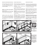
ABFLR
ABFLR
85”
NO ABFLR
87”
ABFLR
wood 2” x 4”
bois 2” x 4”
madera 2” x 4”
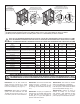
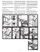
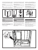
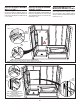
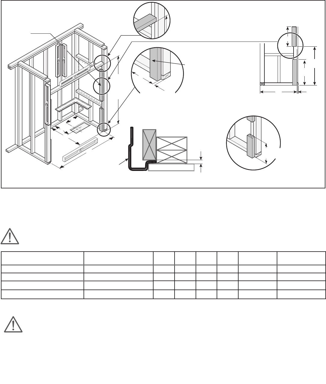
Ensure that the structure meets the
required dimensions, it is level and square.
Place the parts on the front as shown.
When there is a massage
system with Allia TSR-6032 and Allia
TS-6032 the stud must be cut to be able to
push the unit into the alcove.
S’assurer que la structure respecte les
dimensions requises, qu’elle est au niveau
et à l’équerre. Placer les pièces à l’avant
tel qu’illustré.
Lorsqu’il y a un système de
massage avec les modèles Allia TS-6032
et Allia TSR-6032 il faut découper le
montant pour être capable de pousser
l’unité dans l’alcôve.
Asegúrese de que la estructura cumple
con las dimensiones requeridas, que esté
nivelado ya escuadra. Coloque las piezas en
la parte frontal como se muestra.
Cuando se tiene un
sistema de masaje con los modelos Allia
TS-6032 y Allia TSR-6032 se debe recortar
el montante para poder empujar la unidad
dentro del nicho.
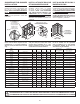
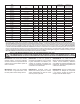
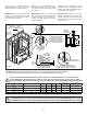
STRUCTURE MEASUREMENTS MUST BE VERIFIED AGAINST THE UNIT
LES DIMENSIONS DE LA STRUCTURE DOIVENT ÊTRE VÉRIFIÉES À PARTIR DES DIMENSIONS DE L’UNITÉ
LAS DIMENSIONES DE LA ESTRUCTURA DEBEN SER VERIFICADAS A PARTIR DE LAS DIMENSIONES DE LA UNIDAD
NOTE: THE FOLLOWING MEASUREMENTS ARE NOT THOSE OF THE UNIT BUT THOSE REQUIRED FOR INSTALLATION (±1/8” (6MM)).
NOTE: LES DIMENSIONS CI-DESSOUS NE SONT PAS CELLES DE L’UNITÉ, MAIS CELLES REQUISES POUR L’INSTALLATION (±1/8” (6MM)).
NOTA: LAS DIMENSIONES INDICADAS A CONTINUACIÓN NO SON LAS DE LA UNIDAD, SINO LAS REQUERIDAS PARA LA INSTALACIÓN (±1/8” (6MM)).
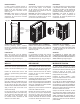
MODEL
MODÈLE
MODELO
No A B C D
Overflow height
Hauteur trop-plein
Altura del rebosadero
Installation Type
Type d’installation
Tipo de la instalación
Allia TSR-6032
2-piece with roof / 2 pièces avec toît
107000-S
60 1/8
(1527)
31 1/4
(794)
16 7/8
(429)
8 1/2
(216)
16 7/8 ABFLR
(429)
Fig. 17.2 , Fig. 21.2b
Allia SHR-6034
2-piece with roof / 2 pièces avec toît
107002-S
60 1/8
(1527)
33 1/4
(845)
17 7/8
(454)
8 1/2
(216)
- Fig. 17.2 , Fig. 21.2b
Allia SHR-4834
2-piece with roof / 2 pièces avec toît
107004-S
48 1/8
(1222)
33 1/4
(845)
17 7/8
(454)
24
(610)
- Fig. 17.2 , Fig. 21.2b
Allia SHR-3636
2-piece with roof / 2 pièces avec toît
107006-S
36 1/8
(918)
35 1/4
(895)
18 7/8
(479)
18
(457)
- Fig. 17.2 , Fig. 21.2b
Fig. 17.2
*
Optional not ABFLR available only on 107000, remove 2” to the ABFLR measurement to obtain not ABFLR.
*
Non ABFLR optionnel disponible seulement pour 107000, enlever 2” de la mesure ABFLR pour obtenir non ABFLR
.
*
No ABFLR opcional disponible solamente en 107000, restar 2” a la medida ABFLR para obtener no ABFLR.