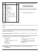
K1022-1005 Installation Instructions Framed Tub / Shower Enclosures: SAVE THESE INSTALLATION INSTRUCTIONS FOR FUTURE REFERENCE AND IN THE EVENT YOU NEED TO ORDER A REPLACEMENT PART. RECORD THE MODEL#___________________ GLASS____________FINISH__________ FROM THE PRODUCT LABEL ON THE PACKAGE IF YOU NEED REPLACEMENT PARTS OR HAVE INSTALLATION QUESTIONS, PLEASE CALL OUR CUSTOMER SERVICE REPRESENTATIVES. T. 1 877 GET-MAAX (1 877 438-6229) F. 1 888 361-2045 www.maax.
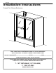
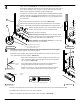
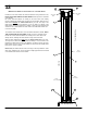
TUB / SHOWER ENCLOSURE 1 11 12 14 6 5 13 6 10 11 15 12 3 8 14 10 3 7 4 9 16 15 18 13 OUTSIDE 17 2
Item No. 1 2 3 4 5 6 7 8 9 10 10 11 12 13 14 15 16 17 18 Part Description Qty.
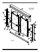
ILLUSTRATIONS OF PARTS 1 - HEADER 3 - WALL CHANNEL 2 - TRACK 5/16" 5 - HANGING BRACKET 7 - TOWEL BAR 6 - #6 SCREW 8 - TOWEL BAR BRACKETS 3/8" 1/4" 9 - DOOR HANDLE 11 - ROLLER 10 - #8 SCREW 7/16" 12 - #8 SCREW 14 - WALL ANCHOR 16 - CENTER GUIDE 1 1/4" 13 - #10 SCREW 15 - BUMPER 17 - END GUIDE 18 - TAPE
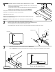
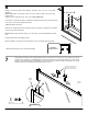
1 WARNING: SAFETY GLASSES SHOULD BE WORN AT ALL TIMES. Measure the finished wall-to-wall distance, dimension “D”, in the center of the Tub / Shower Enclosure ledge. If a steel tape is used, be sure to add the width of the case to the measurement. Subtract 3/16” from dimension “D”, this is your “TRACK D IMENSION”. At this point, re-measure the wall-to-wall distance, dimension “D” and re-check subtraction, to be certain of the correct Track Dimension. “Measure twice, cut once”.
Prepare the Wall Channels for installation by drilling (3) equally spaced mounting holes, as shown in SKETCH 4A. To do this, lay the channel on a flat surface and mark the middle hole and then the two end holes about 3” from each edge at the “V” groove provided. Next, using the “V” groove, drill a 3/16” hole at each marked spot to complete the fabrication of the mounting holes.
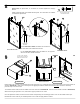
6 Measure the finished wall-to-wall distance, dimension “H”, at the top of the Wall Channels. Please note, that if a steel tape is used, be sure to add the width of the case to the measurement. Subtract 1/16” from dimension “H”, this is your “HEADER DIMENSION”. Dimension H At this point, re-measure the wall-to-wall distance, dimension “H” and re-check subtraction, to be certain of the correct Header Dimension. “Measure twice, cut once”. Measure the “Header Dimension” along the length of the Header.
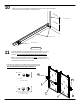
Install Rollers as shown. Please note, the Spacer Nut, on the Roller, is mounted against the Hanging Bracket. 12 Initially, install the Roller in the middle mounting hole. The other holes are available as needed for adjustments. 11 ACTUAL SIZE #8 X 7/16” LONG MACHINE SCREW 12 12 11 11 12 SPACER NUT 11 12 Glass Panel End View Glass Panel End View OUTER GLASS PANEL For the Outer Glass Panel, the Rollers are mounted on the same side as the Towel Bar as shown.
10 Apply Silicone Sealant as shown in SKETCH 10A. Apply to all “seams” created by the Walls / Wall Channels, Track, Track / End Guides, and all around the Center Guide as noted in Step #9. SILICONE SEALANT SILICONE SEALANT SILICONE SEALANT SKETCH 10A 11 Install the Towel Bar and Towel Bar Brackets to the middle of one of the Glass Panel Doors as shown using the #8 x 3/8” Flat Head Screws provided. This is now called the Outer Glass Panel Door.
12 BY THE TOWEL BARS. Install the Inner Glass Panel first. With the Rollers facing toward the Tub, HOLD THE GLASS PANELS BY BOTH SIDES and lift up into the underside of the Header. Be certain that both Rollers are resting on the inner roller track. Slowly release, allowing the Glass Panel to hang from the Header. Slide the Inner Glass Panel towards the shower head end of your Tub. The edge of the Glass Panel should touch the Bumper, if not, the wall is not plumb & the Glass Panel needs to be adjusted.