
Installation Instructions
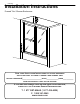

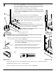
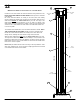

WALL CHANNEL SLIDES DOWN, AROUND
THE TRACK AND END GUIDES, SITTING ON
TOP OF THE EACH PART’S LEGS.
SKETCH 4A
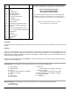
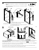
Remove the Wall Channels, Track, and End Guides from the
Shower. Drill mounting holes at the marked locations.
Mounting hole size is as follows:
When mounting to ceramic tile, use a 1/4” masonry drill bit.
Nick the ceramic surface at the mounting hole locations with a
center punch. After drilling, insert Wall Anchors.
When mounting to a fiberglass enclosure, use a 1/8” drill
bit. Wall Anchors are not required.
4
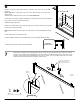
SKETCH 4B
5
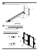
After drilling, clean the Tub / Shower Enclosure ledge and the Wall Channel areas thoroughly.
This will assure proper adhesion of the Silicone Sealant.
Before the Track is installed, apply a bead of Silicone Sealant to the grout line, where the end
of the Track will be located, as shown in SKETCH 5A.
SILICONE
SEALANT
SKETCH 5A
Apply a thick continuous bead of Silicone Sealant to the underside of the
Track. The Silicone Sealant should be applied to the Track’s outside leg
only, as shown in SKETCH 5B.
Do not apply Silicone Sealant to the back side of the Wall Channel.
Sealing the Wall Channel will be completed in the final step.
Position the Track on the Tub / Shower Enclosure ledge in the marked
location. Then, position the End Guides at each end of the Track.
SILICONE
SEALANT
o
f
T
r
a
c
k
U
n
d
e
r
s
i
d
e
SKETCH 5B
Remember, the high side of the Track must be placed toward the outside of the Tub / Shower Enclosure ledge.
Install Wall Channels using the #10 x 1 1/4” Screws provided.
Bumpers are installed in the middle Screw location ONLY, as shown in SKETCH 5C.
ACTUAL SIZE #10 X 1 1/4” LONG SCREW
13
SKETCH 5C
17
2
3
15
13
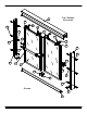
Prepare the Wall Channels for installation by drilling (3) equally spaced mounting
holes, as shown in SKETCH 4A. To do this, lay the channel on a flat surface
and mark the middle hole and then the two end holes about 3” from each edge at
the “V” groove provided. Next, using the “V” groove, drill a 3/16” hole at each
marked spot to complete the fabrication of the mounting holes.
To prepare the mounting surface, carefully position each Wall Channel by sliding
it down, around the Track and End Guide making sure it is “sitting” on top of the
their legs, as shown in SKETCH 4A. Be careful not to move the temporary posi-
tion of the Track.
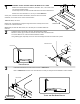
Use a level to plumb the Wall Channel, as shown in SKETCH 4B.
Mark the three mounting hole locations of the Wall Channel on the mounting
surface. Repeat this procedure with the Wall Channel on the opposite wall.
LEVEL