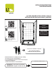
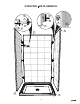
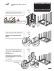
INSTALLATION INSTRUCTIONS GUÍA DE INSTALACIÓN ALCOVE SHOWER INSTALLATION (3 WALLS) INSTALACIÓN DE DUCHA EN NICHO (3 MUROS) HARDWARE INCLUDED IN BOXES HARDWARE INCLUIDO EN LAS CAJAS View Installation Video - Scan QR code with a mobile device OPEN ALL BOXES BEFORE YOU START ABRIR TODAS LAS CAJAS ANTES DE EMPEZAR Ver video de instalación Escanear código QR con un dispositivo móvil. A two person installation is required.
For installation steps in ENGLISH go to page 6 Table of contents: Page Tools and supplies.............................................................................................................. 3 Parts and components........................................................................................................ 4 1. Building the structure..................................................................................................... 6 2. Installing the base..............................
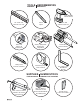
TOOLS HERRAMIENTAS REQUIRED REQUERIDAS 1/8" drill bits Brocas de 1/8 24" level min. Nivel de 24" min. Hole saw Sierra de perforación Utility knife Cuchillo multiuso Pencil Lápiz Electric drill Taladro eléctrico Safety equipment Equipo de seguridad Screwdriver Destornillador Measuring tape Cinta métrica 18" square min. Escuadra de 18" min.
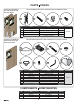
PARTS PIEZAS Inside the sidewall box En el interior de la caja del muro lateral PARTS INCLUDED IN PARTS PACK | PIEZAS INCLUIDAS EN PAQUETE DE PIEZAS 1 n -1 for junctio ar Utile MA n AX -1 for by/p junctio ar Utile IEURE E VIEW IOR INSIDINTÉR VUE INTER – ULOK 303 10060 WALL RE BACK ARRIÈ RIOR MUR POSTE MURO 3 1 3 3 ge daño brisa o damaou or perdid lossde perte de caso 4 IEURE E VIEW IOR INSIDINTÉR VUE INTER VISTA Part Pieza Qty/cant.
OVERVIEW VISTA GENERAL 15 2 9 8 6 1 4 3 14 10 7 INSIDE VIEW VISTA INTERIOR 5 15 14 15 13 5
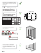
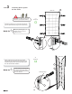
For a worry free installation follow all instructions and check them off as you go. 1 STEP Building the structure Before starting make sure to have all parts and components refer to page 4. Top view of structure 1.1 Check me! Build a structure based on the dimensions in the chart below. C IF STRUCTURE IS ALREADY BUILT CHECK THAT IT RESPECTS THE DIMENSIONS BELOW B COMPATIBLE BASES No.
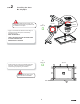
2 STEP Installing the base B3 / Olympia Remove clear plastic film on the base. Use cardboard on the base floor as protection until the installation is complete. 2.1 Check me! Top view Rubber Cardboard Apply a 1/8" width silicone bead around the edge of the drain hole in the base (refer to illustrations). Assemble as shown. HAND TIGHTEN ONLY ! VERIFY THE MAAX LOGO ON THE DRAIN COVER IS FACING THE RIGHT WAY REMOVE EXCESS SILICONE! Threshold 2.
2 STEP Installing the base (cont'd) Olympia COMPATIBLE BASES No. Olympia square 4832 106011 Olympia square 6032 106012 2.3 Check me! Verify that the base is completely level on all sides. Confirm that the drain pipe is centered. We recommend that a plumber completes the drain pipe connection. 13 Leveling the base is critical for wall alignment 2.4 Check me! If needed use wood shims between the studs and the fastening flange to maintain centered position of base.
2 STEP Installing the base (cont'd) B3 2.3 Check me! COMPATIBLE BASES No. B3 Square 4832 B3 Round 4832 B3 Square 4836 B3 Round 4836 B3 Square 6032 B3 Round 6032 B3 Square 6036 B3 Round 6036 420001-5XX 410001-5XX 420003-5XX 410003-5XX 410005-5XX 410005-5XX 410006-5XX 410006-5XX Verify that the base is completely level on all sides. Confirm that the drain pipe is centered. We recommend that a plumber completes the drain pipe connection.
STEP 3 Installing Ulok system on the walls X n -1 for junctio ar by/p Utile X n -1 MAA for junctio ar Utile Skin VIEW EURE OR INSIDE INTÉRI VUE INTERI – ULOK 100603 03 VIEW EURE OR INSIDE INTÉRI VUE INTERI – ULOK 100603 VISTA VISTA WALL E WALL E BACK IOR ARRIÈR MUR POSTER BACK IOR ARRIÈR MUR POSTER MURO MURO 3 3 1 1 WALL CÔTÉ L SIDE DE MUR LATERA MURO WALL CÔTÉ L SIDE DE MUR LATERA MURO 4 4 3 3 of e daño brisa o damag ou or perdid lossde perte de caso case cas in s en
STEP 4 Temporary installation of the back wall 4.1 Check me! Pull back the protective film on the walls (14-15) at least 3" away from all edges. Keep the remaining protective film on the walls. 14 4.2 Check me! Position and level the back wall (14) by sitting it on the threshold at the back of the base. Plumbing the back wall is critical for alignment of the side walls Back wall Quick tip Installing the walls temporarily will ensure proper wall alignment before permanent installation.
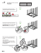
STEP 5 Temporary installation of the side walls 3 5.1 Check me! Install the side wall (15) on the opposite side of the faucet installation. Lift the wall approximately 3" above the threshold of the base, push it completely against the back wall then lower the side wall into position. Side wall 1 Back wall 15 It is critical that all 3 retraction pins engage with the X fasteners. There should be no gap between the walls. Quick tip Quick tip Place a level vertically on the side wall.
STEP 5 Back wall Temporary installation of the side walls (Cont'd) Measure the distance between the front face of the back wall (14) and the center of the faucet. Then measure the distance from the top of the base threshold to the center of the faucet. Top view 5.3 Check me! Faucet center Using those two measurements mark the position of the faucet hole on the remaining side wall. Measure from the side and bottom of the side wall where the retraction pins are installed.
STEP 5 3 Temporary installation of the side walls (Cont'd) Side wall 1 Install the side wall (15) with the drilled faucet hole(s). Lift the wall approximately 3" above the threshold of the base, push it completely against the back wall then lower the side wall into position. 5.6 Check me! Make sure the retraction pins are properly inserted in the X fasteners. There should be no gap between the walls. Quick tip Quick tip The side wall should now line up with the front of the base.
STEP 6 Final installation of back wall Remove all walls from the structure. Clean the shower base and apply a bead of silicone on the threshold at 3/8" from the back fastening flange. Run the bead of silicone the entire length of the base and 1'' on each side also. 6.1 Check me! 6.2 Check me! ⅜" 1" ⅜" 13 Lift and place back wall (14) directly over the silicone without sliding. Verify that the back wall (14) is plumb, shim if needed.
STEP 7 Final installation of side walls 3 Install the side wall (15) opposite the faucet. Lift the wall approximately 3 inches above the threshold of the base, push it completely against the back wall then slide the side wall into position. 7.1 Check me! Side wall 1 Back wall WIPE OFF EXCESS SILICONE Install the side wall (15) with the faucet hole. Lift the wall approximately 3 inches above the threshold of the base, push it completely against the back wall then slide the side wall into position.
STEP 7 Final installation of side walls (cont'd) Check me! Secure the walls to the wall studs with #8 x 1¾ " screws (not included) in the previously drilled holes. Also, secure the walls by the fastening flanges on the sides of the walls. Use the pre-dilled holes. If needed, use shims to keep walls plumb, square and leveled. (Cut shim excess) IMPORTANT: HAND TIGHTEN ONLY. DO NOT OVER-TIGHTEN THE SCREWS.
STEP 9 Silicone Apply a bead of silicone all along the wall to wall and wall to base joints. For a smooth finish you can remove the silicone excess with a damp rag or wet finger. Quick tip Check me! Remove protective film from walls Apply masking tape on both sides of the joint where you will run a bead of silicone. Apply the silicone, smooth with a wet finger then remove the masking tape. All faucets installed on the walls must be sealed with silicone. 10 STEP Glass shelf installation 10.
10 STEP Glass shelf installation (cont'd) 10.2 Check me! Clean the top rubber part of the brackets with a damp cloth, then place the glass shelf (5) over the brackets (6). Quick tip 5 If you can read the MAAX logo, the shelf is installed on the right side. 6 6 10.3 Check me! Insert the washers (8) in the shelf support cap (9). Align and insert the shelf support caps (9) with the holes of the glass and the holes of the shelf brackets (6).
11 STEP Wall finish 10.1 Check me! For the wall finish you can install install your finishing material on top of the flange or on the wall edge as shown.
Para una instalación sin problemas siga las etapas una a una y vaya y marquelas una vez estén terminadas. 1 ETAPA Construcción de la estructura Antes de comenzar asegurese de tener todas las piezas y componentes referirse a la página 4. C t i una estructura Contruir t t que respete t las l dimensiones di i mencionadas en la tabla. C SI LA ESTRUCTURA YA ESTA CONSTRUIDA, ASEGURARSE QUE LAS DIMENSIONES RESPETEN LAS DE LA TABLA BASES COMPATIBLES No.
ETAPA 2 Instalación de la base B3 / Olympia Retire la película transparente de la base. Utilice cartón en el fondo de la base como protección hasta el final de la instalación. 2.1 Marcarme! Arandela de caucho Vista superior Arandela de cartón Aplicar silicona alrededor del agujero de drenaje de la base (ver la ilustración). Montar el desagüe como se ilustra. APRETAR A MANO ÚNICAMENTE! ASEGURARSE QUE EL LOGO DE MAAX UBICADO EN LA CUBIERTA DEL DRENAJE QUEDE ORIENTADO HACIA EL FRENTE DE LA BASE.
ETAPA 2 Instalación de la base (continuación) Olympia Asegúrarse en todos los lados que la base esta perfectamente nivelada. Comprobar que el desagüe está alineado. Se recomienda utilizar una plomero certificado para la conexión de drenaje. BASES COMPATIBLES No. Olympia square 4832 106011 Olympia square 6032 106012 2.3 Marcarme! 13 Es esencial que la base este a nivel para garantizar la verticalidad de las paredes.
ETAPA 2 Instalación de la base (continuación) B3 Asegúrarse en todos los lados que la base esta perfectamente nivelada. Comprobar que el desagüe está alineado. Se recomienda utilizar una plomero certificado para la conexión de drenaje. BASES COMPATIBLES No. B3 Square 4832 B3 Round 4832 B3 Square 4836 B3 Round 4836 B3 Square 6032 B3 Round 6032 B3 Square 6036 B3 Round 6036 420001-5XX 410001-5XX 420003-5XX 410003-5XX 410005-5XX 410005-5XX 410006-5XX 410006-5XX 2.
ETAPA 3 Instalación del sistema Ulok sobre los muros X n -1 for junctio ar Utile for junctio ar by/p Utile INSIDE INTÉRI VUE INTERI 03 1 – ULOK VISTA WALL E BACK IOR ARRIÈR MUR POSTER MURO 3 3 1 1 WALL CÔTÉ L SIDE DE MUR LATERA MURO WALL CÔTÉ L SIDE DE MUR LATERA MURO 4 4 3 3 e daño brisa o damag ou or perdid loss perte de of de case cas caso in s enue en pack incluse empaq this in sont ed ires en este as includ menta are incluid parts supplé están 4 2 VIEW EURE OR INSIDE INTÉ
ETAPA 4 Instalación temporal del muro posterior Retirar al menos 3 o 4 pulgadas de película transparente de todos los lados de la pared posterior. Deje el resto de la película adherida a la pared. Coloque el muro posterior (14) apoyandolo en el umbral posterior de la base y nivelarlo. Es esencial nivelar el muro porterior para garantizar el alineamiento de los muros laterales.
ETAPA 5 Instalación temporal de los muros laterales 3 5.1 Marcarme! Instalar el primer muro lateral (15) en el lado opuesto de la válvula. Coloque el muro aproximadamente 3 pulgadas por encima del umbral de la base, empujando con fuerza contra el muro posterior, a continuación, bajar el muro sobre el umbral de la base. Muro lateral 1 Muro posterior Es esencial que los pasadores estén completamente insertados en los sujetadores en X.
ETAPA 5 Instalación temporal de los muros laterales (continuación) Medir la distancia entre la cara del muro posterior y el centro de la válvula. Medir a continuación la distancia entre el umbral de la base y el centro de la válvula. Muro posterior Vista superior 5.3 Marcarme! Centro de la válvula Pasar las medidas de la posición del hueco de la válvula y marcar subre el muro lateral que aun no ha sido instalado. Medir a partir de la parte inferior del muro y del lado de los pasadores de retracción.
ETAPA 5 3 Instalación temporal de los muros laterales (continuación) Muro lateral 1 5.6 Marcarme! Instalar el muro lateral (15) una vez los agujeros de la válvula han sido perforados. Coloque el muro aproximadamente 3 pulgadas por encima del umbral de la base, empujando con fuerza contra el muro posterior, a continuación, bajar el muro sobre el umbral de la base. Es esencial que los pasadores estén completamente insertados en los sujetadores en X.
ETAPA 6 Instalación final del muro posterior 6.1 Marcarme! Retirar todos los muros de la estructura. Limpiar la base y aplicar una línea de silicona en el umbral de la base a 3/8" de la brida trasera. Aplicar silicona sobre toda la longitud trasera y alrededor de 1 pulgada por lado. 6.2 Marcarme! ⅜" 1" ⅜" 13 Levantar y colocar en su lugar el muro posterior (sin deslizarlo) directamente sobre la silicona.
ETAPA 7 Instalación final de los muros laterales 3 Instalar el muro lateral (15) opuesto al de la válvula. Poner el muro a aproximadamente 3" por encima del umbral de la base, empujarlo a fondo contra el muro posterior y descenderlo sobre el umbral de la base. 7.1 Marcarme! Muro lateral 1 Muro posterior RETIRAR EL EXCESO DE SILICONA. Instalar el muro lateral (15) que tiene los agujeros de la válvula.
ETAPA 7 Instalación final de los muros laterales (continuación) 7.4 Marcarme! Fijar los muros laterales a todos los montantes con tornillos #8 x 1–¾" (no incluidos). Asegurar los muros utilisando los agujeros pre-perforados de la brida. En caso de ser necesario, usar cuñas de madera para asegurarse que los muros están a nivel y verticales. (Cortar el exceso de cuñas) IMPORTANTE: APRETAR A MANO UNICAMENTE. NO APRETAR DEMASIADO LOS TORNILLOS.
ETAPA 9 Silicona Retirar la película de protección de los muros Aplicar una línea de silicona sobre toda la longitud de las uniones (muro a muro y muro a base). Para un buen acabado, retirar el exceso de silicona con un trapo humedo o un dedo humedecido. Consejo rápido Marcarme! Aplicar cinta de enmascarar de cada lado de la unión donde la silicona será aplicada. Aplicar la silicona, emparejar con un dedo humedecido, a continuación retirar la cinta.
10 Instalación de la tableta (continuación) ETAPA 10.2 Marcarme! Limpiar la parte en caucho por encima de los soportes con un trapo humedo. Colocar a continuación la repisa (5) sobre los soportes (6). Consejo rápido 5 La repisa esta en la posición correcta si es posible leer el logo de MAAX. 6 6 10.3 Marcarme! Insertar las tapas de la fijación de repisa (9) en las arandelas (8). Alinear los agujeros de la repisa y los de los soportes (6) e insertar el ensamble de la tapa (9).
ETAPA 11 Acabado del muro Marcarme! Para el acabado del muro, puede instalar su material de acabado sobre la parte superior de la brida o sobre el borde del muro, como se muestra.
LIMITED WARRANTY GARANTÍA LIMITADA MAAX Bath Inc. (hereafter “MAAX”) offers an express limited warranty on each of its products. This warranty extends only to the original owner/end-user for personal household use. For commercial uses, additional limitations apply. MAAX Bath Inc. (a continuación “MAAX”) ofrece un garantía limitada expresa para cada uno de sus productos. Esta garantía va dirigida únicamente al propietario o al usuario original para un uso personal doméstico.