
Installation Guide

5
D
IMENSION
T
D
IMENSION
T / 2
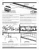
SKETCH 5A
SKETCH 5B
Pencil
line
DETERMINE LOCATION OF CENTER GUIDE HOLE
Remove the Track End Caps and measure the length of the Track
(
DIMENSION T) as shown in SKETCH 5A.
The hole needs to be located in the center of the length of the
Track. Divide T in half (T / 2) and measure “
DIMENSION T / 2” from
one end of the Track as shown.
Mark a line with a pencil at the half-way point on the back-side of
the Track as shown in SKETCH 5B.
Confirm location of pencil line by measuring “
DIMENSION T / 2” from
the other end of the Track. It should be the same location.
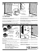
To mark the Height location of the C
ENTER GUIDE HOLE, install the
Center Guide on to the Track as shown in SKETCH 5C.
Slide the Center Guide along the Track until the pencil line shows
through the Screw Boss in the back of the Center Guide as shown
in SKETCH 5D.
Making sure to hold the Center Guide tightly down on to the Track,
insert a pencil in the SCREW BOSS and mark the hole location.
Remove the Center Guide from the Track. Then, using a Center
Punch, make a dimple at the marked location.
This will prevent the drill bit from wandering when drilling the hole.
Carefully drill the hole with the Drill Bit provided.
Install a #6 x 1/2” long Screw into the hole in order to “pre-cut
threads” into the Track. Then remove the screw and set aside.
SKETCH 5C
SKETCH 5D
Pencil line
SCREW BOSS
Pencil line
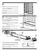
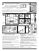
PRE-FIT TRACK
Re-Install Track End Caps (& Corner Adapters, if necessary) on to
the ends of the Track and locate the Track on to tub threshold.
The back of the Track should be located in the approximate center
of the tub threshold as shown in SKETCH 6A.
When the Track positioned correctly, temporarily secure the Track
to the tub threshold with masking tape as shown in SKETCH 6B.
Mark the Track location with a pencil.
SKETCH 6B
O
UTSIDE
tub threshold
I
NSIDE
SKETCH 6A
6
Slide Center Guide
along the Track
2
21
2
TRACK
CENTER GUIDE
TRACK
TRACK
TRACK
ACTUAL S
IZE
#6 X 1/2” LONG
SCREW
20