
Installation Guide

15
ACTUAL SIZE #10 X 3/8” TRUSS HEAD
13
ACTUAL SIZE #10 X 1/4” BARREL BOLT
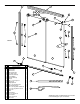
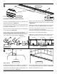
At this point, re-measure the wall-to-wall distance, DIMENSION “H” and re-check subtraction to be
certain of the correct Header Dimension.
“Measure twice, cut once”.
Measure the “HEADER
DIMENSION
” along the length of the Header. Carefully cut the Header to size.
Please note, to obtain the best results, use a 32-tooth per inch hacksaw blade and a miter box.
Slide the Header down on top of the Wall Channels. The Header is reversible.
SKETCH 9A
D
IMENSION
H
10
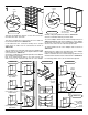
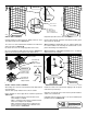
LEFT PANEL
R
IGHT PANEL
PANEL
P
ULL
HOLES
ROLLER M
OUNTING HOLES
SKETCH 10B
SKETCH 10D
SKETCH 10A
Arrange the Glass Panels as they will install in the unit as shown
in SKETCH 10A. Glass Panels shown in front of tub for clarity.
The Panel Pull Holes should be located all the way to the left in the
Left Panel and all the way to the right in the Right Panel.
The Roller mounting holes should be at the top.
Determine which of the Glass Panels will be the
INNER GLASS
PANEL
and the OUTER GLASS PANEL.
For water-sealing purposes, the INNER GLASS PANEL must be on
the same side as the shower head.
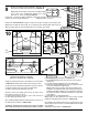
When installing Hanging Brackets and Panel Pulls, orient them on
the Glass Panels as shown in SKETCH 10B.
The Rollers and Panel Pulls install on the inside of an
INNER
GLASS PANEL
and outside of an OUTER GLASS PANEL as shown.
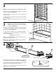
Install Hanging Brackets as shown in SKETCH 10C.
A - Insert Glass Bushings (Gray) into each hole at the top of the
Glass Panel.
B - Carefully slide Hanging Brackets over the Glass Panel.
C - Align hole in Hanging Bracket with hole in the Glass Panel and
secure with #10 Screw and Barrel Bolt.
Please note: It does not matter which side the #10 Screw is
installed on, but if optional Robe Hook (included) is going to be
installed, it should be installed now per instructions included in
the kit and the #10 Screw should be installed on the same side
as the Rollers.
D - Install Rollers on to Hanging Brackets.
Please note: The
NUT attached to the Roller must be located
towards the Hanging Bracket as shown in SKETCH 10D.
As a starting point, Install the Rollers in the mounting hole second
from the top. The other holes are needed for adjustments if the wall
is out-of-plumb.
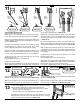
Install Panel Pulls as shown in SKETCH 10E.
INNER GLASS PANEL
Note: INNER GLASS PANEL on left-side shown.
Shower head would be on left side.
Reverse for shower head on right side.
OUTER GLASS PANEL
A B
C
D
14
18
15
13
16
12
NUT installs
against the
Hanging
Bracket
T
UB
UNIT
SKETCH 10E
H
EADER
P
ROFILE
Measure the finished wall-to-wall distance, DIMENSION “H”,
at the top of the Wall Channels as shown in SKETCH 9A.
Please note: If a steel tape is used, be sure to add the width
of the case to the measurement. Subtract 1/16” from
D
IMENSION
“H”, this is your “H
EADER
DIMENSION
”.
9
SKETCH 10C
A
CTUAL S
IZE #8 X 7/16” LONG
MACHINE SCREW
16
THE PANEL PULLS INSTALL ON THE SAME SIDE AS THE ROLLERS.
17
17
17
18