mabe SERVICE MANUAL FOR SEDNA “ESTILO” REFRIGERATORS from Mabe and G.E.
mabe TABLE OF CONTENTS OVERVIEW FEATURES Alarm, vacation mode, levels, turbo mode TECHNICAL DATA Electrical specifications, No-load operation, Cooling unit, Installation AIRFLOW Fan motors, baffle, lines ICE FACTORY Ice tray, filling ice buckets, ice disposal ELECTRONIC CONTROL BOARDS Deluxe electronic control card Basic electronic control board Control display board DEFROST SYSTEM 3
OVERVIEW The new no-frost refrigerator line called “IMAGINATION”, with 13, 15, 17 and 18 cubic foot capacity, is made in the refrigerator factory located in Queretaro, Mexico. The deluxe models (y) have basic electronic controls, while the deluxe models (z) have display systems on the door. Some models include the QUICK FREEZER and vacation mode button options for temperature control and defrost cycle.
FEATURES A. Temperature Control Operation The internal temperatures of the freezer and fresh food compartments can be regulated individually to maintain better food conservation conditions, thus optimizing the use of the appliance. These models feature controls for better temperature monitoring, one for the freezer and one for the fresh food compartment. The freezer control includes the maximum, medium and minimum levels, to adjust the internal air-flow.
Operating Instructions for the External Controls Vacation Mode Directly enabled by pressing the button (when enabled, the indicator light will turn on). It is disabled by pressing the button or by opening the fresh food compartment door for more than 10 seconds. You will also see in the digital display an indicator light that swirls quickly. Turbo Mode Enabled and disabled pressing the button (when enabled, the indicator light will turn on).
Cooling Unit System Forced Air Cooling Unit This kind of system uses fans in the freezer and the condenser area to remove the hot air from the condenser and the refrigerator area.
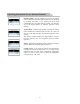
CAPACITOR TO THERMAL PROTECTOR CONNECTION THERMAL PROTECTOR This component (installed in the compressor body) quickly detects any abnormal increase in temperature or excess current caused by a failure of the electrical or mechanical system or an inappropriate application.
mabe SAFETY Before plugging the refrigerator into the electrical outlet, please make sure that: All electrical connections are grounded and all wiring harnesses are connected, away from the sharp edges of the metal plates, and that both the internal and external grounding connections of the appliance are properly connected. ELECTRICAL SYSTEM PTC (POSITIVE TEMPERATURE COEFFICIENT) Unlike an electromechanical relay, the PTC resistor has no coil nor any moveable contacts.
ELECTRICAL SPECIFICATIONS Temperature Control (Level 5) ......................... ( )°F Defrost Control ..................….............…...... 8, 10 AND12 hrs @ 35 min Defrost Thermistor .............................................. °F Voltage: 115V AC 60 Hz ................... Amp Maximum Current Leakage ......................................... 0.75 mA Maximum Grounding Step Resistance ..................... 0.14 Ohms NO-LOAD OPERATION MID/MID Control Position Room Temperature: .........................
DEFROST CIRCUIT The defrost circuit has a series of components that allows the disintegration of the frost formed during the cooling cycle: control board, defrost sensor, relay number 2 in the board, output port in the board, defrost thermostat, fuses and resistance (heater). When the board processor has accumulated an amount of compressor operating time and the sensor records a high resistance value above 8.5 k., the board sends a 12 V.
If the heater is in circuit (on) for 20 minutes in the defrost cycle, the following cycle is increased by 2 hours; if it is connected for 30 minutes, it is maintained as is; if it is connected for 40 minutes, it is decreased by 2 hours. Thus, the defrost cycles are set within the minimum range of 8 hours, maximum range of 12 hours, increasing or decreasing by 2 hours, and no changes are made from 8 to 12 hours or 12 to 8 hours.
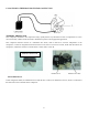
Evaporator fan motor Condenser fan motor assembly 13
For these models THERE ARE 2 DIFFERENT TYPES OF ELECTRONIC BOARD: ONE FOR THE STANDARD AND DELUXE (“X”, “Y”) MODELS, which are models with BASIC ELECTRONICS (see factsheet PTR05014), and ANOTHER ONE FOR SUPERDELUXE (Z) MODELS, which have an EXTERNAL DISPLAY (see the following photos). The different boards that have been used for the Polar, Polar Display and now Sedna models have a different adjustment and/or setting.
BASIC ELECTRONIC BOARD VERSION (“X”& “Y” Models, with Knob) 200D5940G003 Basic Electronic Main Board for Sedna 13’& 15’ Models 200D5940G004 Basic Electronic Main Board for Sedna 17’& 19’ Models These boards have a different adjustment and cannot be exchanged. 3.- OPERATION CHECK. DEFROST CYCLE OPERATION. A) DISASSEMBLE THE CONTROL BOARD AND REMOVE THE EVAPORATOR COVER. B) DE-ENERGIZE THE BOARD (UNPLUG THE BOARD-APPLIANCE WIRING HARNESS). C) BRIDGE J2 AND J5.
DIRECT TEST FOR THE ELECTRONIC BOARD REGULATED VOLTAGE TEST OF THE BOARD The tests described here must be carried out with the sensor located in the fresh food compartment and the potentiometer (temperature control) integrated to the board. In case any of these components is damaged, the whole assembly must be changed because each board is calibrated with these components. When applying a 127 A.C.V. to the white and black cables, the board is energized.
For these models THERE ARE 2 DIFFERENT TYPES OF ELECTRONIC BOARD: ONE FOR THE STANDARD AND DELUXE (“X”, “Y”) MODELS, which are models with BASIC ELECTRONICS (see factsheet PTR05014), and ANOTHER ONE FOR SUPERDELUXE (Z) MODELS (see factsheet PTR05014), which have an EXTERNAL DISPLAY (see the following photos). The different boards that have been used for the Polar, Polar Display and now Sedna models have a different adjustment and/or setting.
When applying voltage to the white and black cables the board is energized and 10 seconds later it sends a signal to the compressor to start working. You must now bridge test points GND and P.P., which will turn off the compressor. Three seconds later, a signal will be sent to the defrost resistance to start working and, at this moment, the white and blue cables must give a reading of 127 A.C.V.
THERMISTOR TEST Thermistors vary their resistance value according to the temperature they detect. For example, at room temperature they have low resistance. When the temperature decreases, the resistance value increases. The following table shows the approximate readings based on a temperature scale. In fact, what is actually important about thermistors is that they must not show a reading of infinite value (open) or zero resistance (closed), and when they turn hot or cold their resistance value must vary.
SPECIAL FEATURES SUPER COOLING FEATURE (QUICK COOLING) When this function is selected, the LED2 light turns on, which indicates that a signal is being sent to the board. When the shut-off temperature indicated by the thermistor and the potentiometer is reached, the board does not send the shutoff signal to the compressor, which continues operating non-stop for an hour. The LED light will turn off when the compressor stops operating.
Evaporator cover assembly Airflow system Defrost system components are: the thermostat, the thermistor and the resistance (heater) Defrost drainage system. The defrost duct is hidden behind the back and the insulating material.
DIAGRAM 22
LIGHT BLUE 23
THE COMPRESOR USE IN SEDNA (ESTILO) REFRIGERATOR IS: COMPRESSOR CBE121L2G DOE/FIDE FOR SEDNA 17´ Y 19´ THE SAME FORM FOR POLAR 16¨AND 18´ IS 3.8 AMPERES. Compressor CBZN100L2 PARA SEDNA 13´ Y 15´ THE SAME FORM FOR POLAR 12´ AND 14´ IS 3.8 AMPERES. OPERATING PRESSURES: LOW SIDE AND HIGH SIDE : De acuerdo al plano estos son los valores para el SEDNA According to the Label these are the values for sedna (Estilo) is the following.
PROBLEM 1 - The refrigerator does not cool (the compressor and the light bulb do not work). FAILURE No power in the contacts. The wiring harness is disconnected or making a false contact. SOLUTION Check contacts. Connect pins or replace wiring harness. 2- The refrigerator does not cool (the compressor does not work, but the light bulb works). Potentiometer knob (temperature control) in 0 position. The electronic board does not send a signal for the compressor to start operating.