IP Office IP DECT Installation 15-601085 Issue 04f - (11 June 2009)
© 2009 AVAYA All Rights Reserved. Notice While reasonable efforts were made to ensure that the information in this document was complete and accurate at the time of printing, Avaya Inc. can assume no liability for any errors. Changes and corrections to the information in this document may be incorporated in future releases. Documentation Disclaimer Avaya Inc.
Contents ..................................................................... 101 7.3 IP Signalling and Media Stream 7.4 WML Tags ..................................................................... 104 7.5 IP DECT SAP Codes ..................................................................... 105 Index ...............................................................................107 Contents 1. IP DECT 1.1 Base Stations ..................................................................... 9 ...........
Chapter 1.
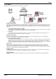
IP DECT: 1. IP DECT The DECT over IP system comprises the following components: · IP DECT Base Stations These are connected to the LAN. Up to 32 base stations are supported for IP Office, with each able to host up to 8 simultaneous calls. Different models of bases station are available for indoor and outdoor location usage, using either mains outlet power or Power over Ethernet (PoE). The base stations use G711, G723.1 and G729ab on the LAN side.
Additional Components In addition to the components above, the IP DECT system can utilize the following additional services: · LDAP or TFTP Server A directory of telephone numbers can be retrieved from an LDAP or TFTP server and displayed on IP DECT handsets. With IP Office, the IP Office control unit can act as the TFTP server source for its own user numbers and external directory numbers. · SysLog Server The IP DECT base stations can output SysLog events to a SysLog server.
IP DECT: 1.1 Base Stations When used with IP Office, the IP DECT supports up to 32 base stations. One base station is designated during installation as the Avaya DECT Mobility Manager (ADMM) and is used to configure and control the IP DECT system. Note that a base station is also called a Radio Fixed Part or RFP. The following types of base station are supported for use with IP Office: · RFP31: Indoor Base Station No longer available and not supported in North America.
Aerials By default all the base stations are supplied with omni-directional aerials. For the RFP31 and RFP32 base stations the aerials are integral and cannot be changed. For the RFP33 and RF34, the aerials are connected by TNC connectors and can be replaced with beam or dipole aerials. The use of beam aerials is not supported in North America. The use of thirdparty aerials is not supported by Avaya. RFP31 This base station is for indoor use only.
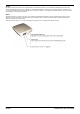
IP DECT: Base Stations RFP32 This base station is for indoor use only. It has integral omni-directional aerials and can be powered by either a mains adapter or by 802.3af Power over Ethernet supply. The RFP32 has 3 separate LEDs in red, orange and green showing the different states during startup and operation. RFP33 This base station can be used indoors and outdoors. It has two external omni-directional aerials. The base station can only be powered using an 802.3af Power over Ethernet supply.
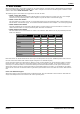
The following technical specification is applicable to the currently available IP DECT base stations. Dimension RFP32 RFP34 Aerials 2 Internal. 2 External. TNC connectors. Power over Ethernet Class 0. Class 0. Ambient Temperature -5°C to +45°C/23°F to 113°F. -25°C to +55°C/-13°F to 131°F. Relative Humidity 5 to 95% non-condensing. 5 to 95% non-condensing. Current Consumption 120mA. 120mA. Power 6W. 6W. Type of Ingress Protection IP20. IP55. Flame Resistance UL94 V0-5VB. UL94 V0.
IP DECT: Base Stations 1.2 3701 IP DECT This IP DECT phone is not supported in North America. · Listen-only hands free speaker. · SOS Emergency key for speed dialing an emergency number. · Information key that can be used for: · Phone number lists and voice mail indication. · Information and speaker key flash when active. · 50 phone book entries in every handset · 10 possible ring tones with temporary mute. · 4-level signal strength display. · Speaker and handset volume, 3-levels and mute capability.
1.3 3711 IP DECT The 3711 phone supports the same features as the 3701 IP DECT handset but with the following differences: · Full hands-free speakerphone operation. · Headset connection (2.5 mm jack). · Vibrating alarm. · Personal phone book with 100 entries · Access to system phone book. · Voice Mail indication. · Choice from 30 ring tones. · Speaker and handset volume, 7-levels and mute capability. · Automatic call pick-up using a headset.
IP DECT: 3711 IP DECT 1.4 Licensing The IP DECT solution requires a license entered into the main base station's (ADMM) configuration in order to operate. This license is based on a number of factors: · A transaction ID supplied when ordering the IP DECT system. · A serial number generated from the MAC addresses of some of the base systems within the IP DECT system. · The number of base station MAC addresses used for this varies with the total number of base stations needed with the system.
1.5 System Capacities The maximum number of simultaneous calls is limited by the number of VCM channels of the IP Office and the channels of the IP Base Stations. The maximum number of simultaneous calls can also be affected by the direct media configuration in the IP Office Manager. Base Stations The IP DECT base stations have the following capacity. · Up to a maximum of 32 base stations are supported. · 1 base station must be set as the ADMM. This does not affect the base stations call handling.
IP DECT: System Capacities 1.6 Technical Specification Digital Enhanced Cordless Telecommunication (DECT) The standard (ETS 300 175) essentially specifies the air interface, known as the radio interface. Voice and data can both be transmitted via this interface. DECT technical characteristics are: · United States: · Frequency Range: 1.920 to 1.930 GHz (10MHz bandwidth). · Carrier Frequencies: 5 (1.728 MHz spacing) with 12 time slots each. · Transmit Power: 20dBm.
1.7 IP DECT Software The software for installation of an IP DECT system with IP Office is included on the IP Office Administrator Application CD. The files are located in the folder IPDECT. The files are as follows (note that the actual file names include version labels which may vary): File Description ADM_Configurator.jar This is a configuration tool for the static IP address setup of base stations. It requires the PC to have JVM 1.1.4 (Java Virtual Machine) installed.
Chapter 2.
2. Site Survey and Planning Coverage In Theory Given ideal open field conditions, the range between a handset and base station can be up to 600 metres (approximately 2000 feet). However where obstacles absorb signal strength and reflected signals giving increased error rates, the range is more realistically between 30 metres (98 feet) indoors and 300 metres (984 feet) outdoors. Coverage In Practice In practice, no rules or guarantees can be given for base station coverage.
Site Survey and Planning: Performing a Site Survey We cannot give precise recommendations for a site survey as every site will vary. However a site survey is a prerequisite to installation in all cases. The correct and effective placement of base stations will prevent problems and maximize coverage. Site survey kits are available from Avaya. These contain a specially adapted base station that is able to operate independently. The kit also includes handsets and necessary chargers.
2.1 Base Station Synchronization To allow call handover when a caller moves from the coverage area of one base station to another, the base stations need to exchange synchronization signals. They do this using wireless signalling between the base stations. This therefore requires the base station coverage areas to overlap. For one IP base station to synchronize to another IP Base Station, the signal strength cannot drop below –70 dBm. You must consider this requirement during the site survey.
Site Survey and Planning: Base Station Synchronization 2.
System Details Information Details Note System Name TAN PARK ID Obtained during installation. Serial Number Obtained during installation. License Key Obtained during installation.
Site Survey and Planning: IP DECT System Planning Base Stations Obtain a building plan to use for the site survey and record the locations of the base stations on that plan. Base station not using PoE will require a power supply unit and access to a mains power outlet within 1 metre (3 feet) of the base station.
Handsets The number must be unique and within the requirements and restrictions of the IP Office system. Refer to the IP Office Manager documentation.
Chapter 3.
3. Base Station Installation This section does not cover the physical installation of the base stations, ie. wall mounting and connection of power supplies. That should be done in accordance with the information provided with the base stations. This section covers the software configuration of the base stations. Installation Stages · TFTP Server Setup Required to provide software to the IP DECT base stations.
Base Station Installation: · ¨ TFTP Server IP Address (Mandatory). · ¨ TFTP File Name (Mandatory). · ¨ ADMM Base Station IP Address (Mandatory). · ¨ Default Gateway IP Address (Optional). · ¨ DNS Address (Optional). · ¨ DNS Domain (Optional). · ¨ Broadcast Address (Optional). · ¨ NTP Server Address (Optional). · ¨ Syslog IP Address (Optional). · ¨ Syslog Port (Optional). · ¨ VLAN ID (Optional). Tools Required · ¨ IP Office Manager PC with IP Office Manager.
3.1 TFTP Server Setup Follows a base station restart or loss of power, each base station retains only its IP address settings (if it has been statically configured). If not statically configured the base station needs to obtain its IP address settings via DHCP. In either case the base stations then need to upload from a TFTP server the IP DECT base station software before they become operational again. Therefore there is a requirement for the IP DECT system to have permanent access to a TFTP server.
Base Station Installation: TFTP Server Setup 3.2 Static Base Station Configuration This stage covers configuring the IP address settings of the base stations. This is best done before the base stations are mounted in position. · This process uses static IP address setup. If DHCP address setup is required see Dynamic Base Station Configuration 34 . Prerequisites · The TFTP Server must be running and tested. See TFTP Server Setup 30 .
Process 1. For this process the PC, the base station and TFTP server should all be connected to the same LAN. 2. If the TFTP server provides any view of file requests and transfers, it will be useful to have that view visible during this process. 3. Apply power to the base station. 4. Locate the IP DECT folder on the IP Office Administrator Applications CD or DVD. 5. Double-click on the ADM_Configurator_1_1_5.jar file (the version number may vary). 6. This tools needs Java Runtime Environment version 1.
Base Station Installation: Static Base Station Configuration 16.Click Send Configuration. The response at the bottom left should be send ok. Click Reset Configuration and then List Configuration to confirm the settings sent to the base station. 17.If the settings are correct, the base station will request the base station software file from the TFTP server.
3.3 Using IP Office DHCP The IP DECT base stations can be installed using DHCP if a DHCP server is available. This can include using the IP Office as the DHCP server if no other DHCP is present on the network. The process below covers use of the IP Office. If a 3rd party DHCP server is to be used, refer to the DHCP Server Operation 98 notes in the appendix. Prerequisites · The TFTP Server must be running and tested. See 2. TFTP Server Setup 30 .
Base Station Installation: Using IP Office DHCP DHCP Using IP Office 1. Note that this process require the IP Office to reboot and so will end all currently connected calls and services. 2. Start IP Office Manager and click 3. In the left hand pane select to receive the configuration from the IP Office system. System. 4. On the System tab, ensure that the TFTP Server IP Address is set correctly. Click OK.
9. Click on the Gateway tab. · In the Gateway IP Address field, enter the IP address that the DHCP server should reserve for the base station that will act as the ADMM. Ensure that this address is within the range of dynamic addresses the IP Office can assign. · The remaining fields should only be changed from their defaults if required. Their functions are described below: · Compression Mode Select the compression mode from the drop down list.
Base Station Installation: Using IP Office DHCP 12.Depending on which application is performing TFTP, it should show the base stations requesting and downloading their application software. 13.The LED or LED's on the base stations should show their status. Check these. Power cycle the base stations if necessary to restart them. · RED On Wait for link up. · RED Flashing 0.5 Hz Launching a DHCP request and waiting for a DHCP offer. · RED Flashing 2.5 Hz Downloading the application image.
3.4 Create an IP DECT Line It is not possible to create more than one IP DECT Line. Warning · Adding a line requires the IP Office to be rebooted. That will end any current calls and services on the IP Office. Information Required · ¨ IP Office Login Service user name and password with Administrator or Manager security group rights for the IP Office. Those rights are required in order to create new extensions. · ¨ ADMM Details The IP address and MAC address of the base station acting as the ADMM.
Base Station Installation: Create an IP DECT Line 7. Click on the Gateway tab. · In the Gateway IP Address field, enter the IP address of the ADMM base station. · The remaining fields should only be changed from their defaults if required. Their functions are described below: · Compression Mode Select the compression mode from the drop down list. · Gain This field allows the audio signal strength for calls between the IP Office and IP DECT extension to be adjusted. · Silence Suppression When selected, H.
3.5 ADMM Setup This sequence is applicable only to a simple IP DECT system with all base stations in the same IP region and the same cluster. Information Required · ¨ Base Station Details The base station MAC addresses and the clusters. · ¨ IP Office Details The IP address of the LAN connection to the IP Office. Tools Required · ¨ Web Browser Used for web access to the ADMM configuration. Process 1. Start the web browser. 2. Enter http:// followed by the IP address of the ADMM base station. 3.
Base Station Installation: ADMM Setup 6. Click IP Regions. · Click New. · Set the ID to 1. · Enter a Name such as IP Office. · Select the correct Time Zone. · Click OK. 7. Select IP DECT Base Stations. · Click New. · Add the MAC Address of the base station. · In Location enter a note of its physical location. · Set the IP Region to match the ID of the one just created, for example 1. · Select the tick box next to DECT Settings. · Enter the cluster number for the DECT cluster, for example 1. · Click OK.
· For Server Name enter the IP address of the IP Office LAN to which the IP DECT system is connected (LAN1 or LAN2). · For Internal List enter nasystem/user_list7. · For Extenal List enter nasystem/dir_list. · Click OK. 12.Select System and then System Settings. · The Time Zone should now reflect that selected for the IP Region. · Set the Local Time and the Locale Date correctly. 13.Click OK. 14.For most systems that completes the general setup. 15.
Base Station Installation: ADMM Setup 3.6 ADMM Licensing This process enters the license key required by the ADMM to enable IP DECT operation. It used the web server interface of the ADMM. Information Required · ¨ TAN (Transaction ID Number) This number is provided with the IP DECT system when ordered. · ¨ Base Station MAC Addresses MAC Addresses of the base stations selected for license validation. · ¨ Licensing Site URL http://licence.aastra-detewe.de/Avaya.
6. Under 1st Step, click New. · Enter the MAC address or addresses of the base stations chosen for licensing. · Click OK. The MAC address should be listed with a green tick indicating that the base station is connected to the ADMM. 7. The menu now contains a Serial Number. Using this serial number and the TAN transaction ID number from the IP DECT delivery note you will now be able to obtain a license key for the IP DECT system from http://licence. aastra-detewe.de/Avaya. 8.
Chapter 4.
4. Handset Installation This section is divided into the following sections: · Upgrade the Phone Firmware. 47 It may be necessary to upgrade the existing firmware on the supplied IP DECT handsets to match the software being used by the IP DECT base stations. The necessary software to do this firmware upgrade are included on the IP Office Administrator Applications CD or DVD. A special serial or USB cable is required for the PC to handset connection required during the firmware upgrade.
Handset Installation: 4.1 Upgrading the Phone Firmware The firmware on the 3701 and 3711 phones can be upgraded. This is done by connecting a special serial or USB cable to the phone. You should upgrade the firmware on all phones to that provided on the same IP Office Administrator Applications CD or DVD from which the software for the IP DECT base stations was also taken. Tools Required: · ¨ IP DECT Phone Upgrade Cable Two types of cable are available, serial and USB.
Upgrading 3701 Phone Firmware (Serial Cable) 1. Connect the 3701 phone to your PC’s serial interface using the serial cable. 2. Open the IP Office Administrator Applications CD or DVD and locate the IP DECT folder. 3. Double-click on the up_avaya3701_xx.xx.xx.exe file (the version number may vary). 4. Click Continue. 5. Select the port to which the download adaptor is connected. 6. The process can be logged to a file. If required select Log update procedure box and specify the logfile path and name.
Handset Installation: Upgrading the Phone Firmware 7. Click Continue. 8. When the update has completed, either exit the program or insert the next phone that requires upgrading to the cradle and restart the upgrade process.
Upgrading 3711 Phone Firmware (Serial Cable) 1. Connect the 3711 phone to your PC’s serial interface using the serial cable. 2. Open the IP Office Administrator Applications CD or DVD and locate the IP DECT folder. 3. Double-click on the up_avaya3711_v3_and_v2_xx.xx.xx.exe file (the version number may vary). 4. Click Next. The application will search for the phone and then display its details. 5. If the connected 3711 is identified by the Installer, the 3711 is switched off. 6.
Handset Installation: Upgrading the Phone Firmware 4.2 Adding Handsets to ADMM This process below is divided into a number of stages. These are: 1. Obtaining the unique IPEI serial number of an IP DECT handset. 2. Creating an entry for the handset in the ADMM configuration. 3. Enabling handset subscription on the ADMM. 4. Subscribing handsets. 5. Disabling further handset subscription on the ADMM. Pre-Requisites 1.
Process 1. Stage 1: Obtaining the Handset IPEI The IPEI is a serial number unique to each handset. An entry for the handset with the matching IPEI must exist in the ADMM configuration before the handset can subscribe to the IP DECT system. For 3701 and 3711 handsets the IPEI can be obtained as follows: 1.1. Power on the handset. 1.2. Press Menu. 1.3. Select System | Subscription | IPEI. Note the number displayed. 1.4. Press Esc to return the phone to the normal standby menu. 2.
Handset Installation: Adding Handsets to ADMM 5. Stage 5: Disable Phone Subscription We recommend that you disable the subscription of further phones. 5.1. Using the web browser to access the ADMM configuration, on the IP DECT Handset page the subscribed handsets should now be listed. 5.2. Click Stop to disable further subscriptions. 5.3. Logout of the ADMM configuration. 6.
4.3 IP Office User Creation For each IP DECT handset, matching extensions have to be created within both the IP Office configuration and the ADMM configuration. This section covers the creation of IP DECT extensions (and their associated users) within the IP Office configuration. The DECT Extension menu will only be active if at least one IP DECT Line has been configured. Up to 120 IP DECT extensions may be created.
Handset Installation: IP Office User Creation 7. Select the IP DECT tab. · The DECT Line ID should already show the ADMM base station IP address. · Select the Message Waiting Lamp Indication Type to either On or None. · Click OK. 8. If the extension number is new, IP Office Manager will prompt Do you wish to create an associated user?. Select Yes. 9. Manager will automatically jump to the User entries section and show the details for the new user. 10.
Chapter 5.
5. ADMM Web Access The ADMM base station acts as an HTTP web server. This allows it to be accessed and configured across the network using a web browser. · The web server uses the ADMM's IP address and port 80. · Access is restricted to one active session at a time with an idle time out (5 minutes). · The browser used for service access has to be at least Microsoft Internet Explorer 6.0 or Mozilla Firefox 1.0 and must have frame support, javascript and cookies enabled.
ADMM Web Access: 6. If login is successful the ADMM configuration Home menu is displayed. You can return to this menu from any submenu by clicking on Home. 7. If this interface is idle for 5 minutes you will be automatically logged off. 8. To exit the system manually, click Logout. · If the browser is closed without logging out first, the service access will be blocked for 5 minutes.
5.1 System Menu This option is used to access a series of menus for various system settings. 1. Using a web browser login to the ADMM base station. 2. From the Home menu select System. 3. Select the required sub-menu.
ADMM Web Access: System Menu 5.1.1 System | System Settings The system settings cover global settings of the ADMM such as the system name. 1. Using a web browser login to the ADMM base station. 2. From the Home menu select System. 3. Select System Settings. · Restart This command allows you to restart the ADMM base stations and also to erase the current configuration if required. See Restarting 85 .
· Syslog The IP DECT base stations can output RFC 3164 syslog messages. Those messages can be viewed using standard Syslog tools (not part of the IP Office or IP DECT software suite). · IP Address Enter the IP address of the Syslog server. · Port Enter the port on which the Syslog server is configured to receive Syslog messages. · Date and Time The time and date are shown on the display of 3711 phones when idle.
ADMM Web Access: System Menu 5.1.2 System | User Account This menu is used to set the name and password used for web access to the ADMM. 1. Using a web browser login to the ADMM base station. 2. From the Home menu select System. 3. Select User Account. 4. Enter the User Name and Password required. Note that the values are case sensitive.
5.1.3 System | Time Zone The local time and date displayed on the 3711 phone, depend on the IP region the IP DECT phones are located in. Each IP region is configured to a certain time zone. Based on this, the local time can be calculated individually (depending on the current date and the daylight savings time rule). In the time zone section, the ADMM provides all available time zones. They are set per default with their known daylight savings time rules adjusted to the Universal Coordinated Time (UTC).
ADMM Web Access: System Menu 9. If the time zone has no DST only the UTC difference can be configured. For the DST, both points of time (begin of standard time and begin of daylight savings time) have to be specified exactly. A certain day in the month or a certain week day in a month can be used, as shown in the following figure: 10.Click OK.
5.1.4 System | SNMP Each base station can act as an SNMP agent. If SNMP is enabled through the ADMM, the base stations will give alarm information to an SNMP server at the specified address and allows SNMP management software such as HP OpenView to view the network. The base station SNMP agent supports SNMPv1 and SNMPv2c. The agent does not support MIB-II write access, SNMPv2MIB read/write access, NET-SNMP-MIB read/write access, NET-SNMP-AGENT-MIB read/write access and SNMPv3.
ADMM Web Access: System Menu 5.1.5 System | Backup The ADMM web interface allows copies of the configuration to be save and loaded to the browser PC. 1. Using a web browser login to the ADMM base station. 2. From the Home menu select System. 3. Select Backup. · Save This option will start a dialogue to save a copy of the current configuration to a file on the browser PC. · Restore Configuration Restoring a previously saved configuration. Use of this option causes the ADMM base station to restart.
5.2 IP Regions An IP Region is used to define a relation between a IP Base Station and the IP Trunks which have to be used to communicate with the Avaya communication server. For IP Office only one IP region should be created. The IP region must be created before IP DECT base stations or an IP trunk can be added. 1. Using a web browser login to the ADMM base station. 2. From the Home menu select IP Regions. · To view the settings of an existing region click on the · To delete a region click on the icon.
ADMM Web Access: IP Regions 5.3 IP DECT Base Stations This menu lists all configured IP DECT base stations including the ADMM base station. · Clusters To ensure the hand over of a phone between base stations during a call, all base in a physical area need to synchronize with each other by exchanging wireless signals. See Base Station Synchronization 22 . This is achieved by placing the IP Base Stations sufficiently close to each other that each base station is in range of at least one other base station.
· IP Region The IP region with which the base station operates. The regions need to be created before the base station can be assigned. · DECT Settings This option can be used to disable the DECT service of a base station. This option is used chiefly for the ADMM base station. If the ADMM is used for DECT, up to 50 simultaneous calls are supported on the IP DECT system. If the ADMM base station is not providing DECT, up to 100 simultaneous calls are supported on the IP DECT system.
ADMM Web Access: IP DECT Base Stations IP DECT Base Station States For each IP Base Station the state of the DECT subsystem is displayed. The states are: · Synchronous The IP Base Station is up and running. The IP Base Station recognises and is recognised by other IP Base Stations in its cluster through its air interface and delivers a synchronous clock signal to the phones. · Asynchronous but active The IP DECT Base Station has not been able to synchronize to its neighbours yet.
5.4 IP Trunks An IP trunk must be defined for the signalling between the ADMM base station and the IP Office. The same trunk is also defined in the IP Office configuration. Only one trunk is supported for IP DECT with IP Office. IP trunks can be added to the system by clicking New. A pop up window appears, providing the configuration of a new trunk. Before a trunk can be added, the associated IP region has to be already configured. · Name Enter a name that will help identify the connection. · ADMM Port.
ADMM Web Access: IP Trunks 5.5 IP DECT Handsets This page shows all the know IP DECT extensions and allows subscription 51 of those phones to the system. · New This option is used to add the details of a new handset prior to its subscription, see below. · Subscribe Click this option to allow the subscription of currently unsubscribed handsets. When that action is no longer required click Stop to disable any further subscriptions.
A new phone can be added to the system by pressing New. The following pop up window appears allowing the configuration of a new phone: · Type The type of phone will be automatically detected (in the case of the 3701 and 3711 phones). If the type of phone cannot be detected, it will automatically be set to WT9620. · If the type (WT9620, 20DT, GAP) of phone is configured before subscription and the type cannot be detected then the configured type will be used.
ADMM Web Access: IP DECT Handsets 5.6 System Features This set of menus provide options that may need to be changed to maximize IP DECT system feature interaction with the telephone system, in this case IP Office. 1. Using a web browser login to the ADMM base station. 2. From the Home menu select System Features. 3. Select the required sub-menu.
5.6.1 System Features | Voice Mail This menu can be used to configure the number that handsets should use to access the switches voicemail. For IP Office operation this number should be a system short code that routes to the IP Office's voicemail server. 1. Note: Changes to these settings are not shown on handsets until Update is selected on the IP DECT Handsets 73 menu. Handset user can also set this number themselves using Menu | Telephone Option | Voice Box no on the handset. 2.
ADMM Web Access: System Features 5.6.2 System Features | Media Server Features This menu allows you to configure the media server feature available to the IP DECT phones and the associated signalling to the media server (IP Office) necessary for those features. The settings are is sub-divided into those available to the phone when idle and those available when active. These are features available through the display menus on the phones.
· Call Forward All: *01 · Call Forward Busy/No Reply: *03 or *05 · Call Forward Cancel: *00 · Call Unpark: *38* · Transfer: Not supported by short code. · Enquiry: Not supported by short code. · Conference: *47 · Call Park: *37* 5. Click OK.
ADMM Web Access: System Features 5.6.3 System Features | Digit Treatment This menu allows you to configure the IP DECT system to alter the dialing resulting from numbers received via the directory and WML features. The digit treatment takes place before the number is transmitted to the handset menu. The digits are treated in two steps: · First all invalid characters like space or hyphens are removed from the number. For example +49 (30) 6104 4492 will be substituted by +493061044492.
5.6.4 System Features | Directory The IP DECT system can provide the IP DECT phones with access to a directory of numbers, obtained either using TFTP or LDAP. For IP Office installations, the desirable option is to configure TFTP access to obtain the directory of IP Office users and the IP Office external number directory. 1. Note: Changes to these settings are not shown on handsets until Update is selected on the IP DECT Handsets menu. 73 2. Using a web browser login to the ADMM base station. 3.
ADMM Web Access: System Features TFTP Based Directory The following fields for obtaining a TFTP based directory can be edited, if the Type is set as TFTP. · Server Name Set this to the IP address of the IP Office control unit. · Server Port: Default = 69. The default is the port on which the IP Office control unit listens for TFTP requests. · Internal List: Default = nasystem/user_list7 This is the path and file. It can be up to 127 characters. The default is the IP Office user list (nasystem/user_list7).
LDAP Based Directory The following fields for obtaining an LDAP based directory can be edited, if the Type is set as LDAP. · Server Name and Port The LDAP server name or IP address. · Server Port: Default 389. The LDAP port on that server. Note SSL is not supported. · Search Base The LDAP query string to retrieve the names from the company database and store the information on the ADMM base station. For example ou=people,o=avaya.com. · User Name and Password A user name and password if required.
ADMM Web Access: System Features 5.6.5 System Features | WML The 3711 phone supports WAP WML web site browsing. This menu can be used to enable WML support and to add up to 9 pre-set WML web site URL's to the phone's directory. 1. Note: Changes to these settings are not shown on handsets until Update is selected on the IP DECT Handsets menu. 73 2. Using a web browser login to the ADMM base station. 3. From the Home menu select System Features. 4. Select WML. 5.
5.7 ADMM Licensing The ADMM web interface can be used to view and manage the IP DECT system licenses. The license is both based on and controls the number of base stations supported 1. Note: Making changes to the license settings causes the IP DECT system to restart and disconnects all calls in progress. 2. Using a web browser login to the ADMM base station. 3. From the Home menu select Licensing. This screen shows the status of the licenses entered with the ADMM configuration.
ADMM Web Access: ADMM Licensing 5.8 Restarting the ADMM This menu can be used to manually restart the ADMM if required. Doing this will terminate all current calls on the IP DECT system. 1. From the Home menu select System. 2. Select System Settings 3. Click Restart. 4. The Discard All Settings option can be used to reset the configuration. Only select this option if absolutely necessary. 5. Click OK. 6. The following message is displayed: 7. The ADMM web login page is displayed after the ADMM restarts.
Chapter 6.
6. Maintenance 6.1 Phone Maintenance The IP DECT 3701 and 3711 handsets provide a number of maintenance and diagnostics functions. These are accessed by pressing Menu and then dialing the sequence R***76#. Checking the 3701 Phone Firmware Version 1. Press Menu. 2. Enter R***76#. 3. Select Version Number. 4. Press OK. 5. The display will show the software and the hardware level of the phone. 6. To stop the test, switch the phone off and on again.
Maintenance: Phone Maintenance Change the Phone Security PIN 1. Press Menu. 2. Enter R***76#. 3. Select Change PIN and press OK. 4. Enter the new PIN and press OK. 5. Enter the new PIN again and press OK. Site Survey Mode This function puts the phone in the 'site survey mode'. While in this mode the phone can also receive a call to allow audible checking of the call quality as you move around the survey area. . 1. Press Menu. 2. Enter R***76#. 3. Select Site Survey. 4. Press OK. 5. Press Esc. 6.
6.2 DECT Monitor DECT Monitor is an Windows program that gives a real time overview of the IP DECT system including the operation of phones and base stations. This tool imposes a processing load on the ADMM and so should only be used when absolutely required. It operation is enabled/disabled though the DECT monitor setting within the ADMM configuration. DECT Monitor Software 1. The DECT Monitor software (DECTNetmonitor.
Maintenance: DECT Monitor 5. On DECT monitor has established communication with the ADMM base station, information about the IP DECT system is displayed. The level of detail can be adjusted and details can be recorded to a log file is required. 6. When use of DECT Monitor is completed, close the application. 7. Disable the DECT Monitor setting within the ADMM base station configuration.
DECT Monitor Notes When all links have been established, the DECT data of the system are automatically read out and entered in the tables RFP-Table and PP-Table. This procedure is called Config Request. Next, the defined trace options (Event Mask) are sent to the ADMM. The options which are sent to the ADMM are always those which were active the last time the program was exited. If the trace option Transaction establish/release is activated, the ADMM will deliver all existing transactions.
Maintenance: DECT Monitor 6.3 SMNP In order to manage a large network of IP DECT Base Stations, an SNMP agent is offered in each IP DECT Base Station. · The SNMP agent responds to SNMPv1 and SNMPv2c read requests for the standard MIB-II objects. · The agent supports both SNMPv1 and SNMPv2c traps ('coldStart', 'nsNotifyShutdown', 'authenticationFailure’ and 'nsNotifyRestart').
6.4 Syslog Output The ADMM and the IP Base Stations are capable of propagating syslog messages conforming to RFC 3164. This feature together with the IP address of a host collecting these messages can be configured. The output of Syslog events is enabled using one of the following methods: · DHCP using public option 227 and 228. · Local configuration via the ADMM Configurator tool. · Setting syslog daemon server and port via ADMM base station web access.
Maintenance: Syslog Output 6.5 Base Station Telnet Interface Each IP Base Station, including the ADMM, can be accessed using Telnet. This allows for diagnostics and various actions when OMM is not available. General Telnet Access 1. Open a Telnet session to the IP Base Station. 2. Username is iprfp. 3. Password is crftpw. Welcome to IP RFP OpenMobility Avaya Version x.y.z Fr Apr 29 12:34:06 CEST 2005 Release (BUILD 0) 172.30.111.232 login: iprfp Password: Welcome to the system usershell! 172.030.111.
Removing the Local Configuration You can remove the local configuration settings of the IP Base Station using the telnet interface of an IP Base Station. 1. Start a telnet session using the IP address of the IP Base Station. 2. Enter login: root and password: avaya12. 3. Enter local_db -c. 4. All local network settings are removed.
Chapter 7.
7. Appendix 7.1 DHCP Server Operation A third-party DHCP server can be used to provide the IP address information required by the IP DECT base stations. The table below indicates the information that can be provided through DHCP. Option Usage Notes – IP Address Mandatory The IP address is taken from the yiaddr field in the DHCP message. – Netmask Mandatory The IP netmask is taken from the subnet mask option (code 1).
Appendix: DHCP Server Operation 7.2 802.1Q VLAN Support The IP Base Stations support VLANs according to IEEE 802.1Q. VLAN can be administered either: · On a per port basis of the LAN switch assuming that the IP Base Stations are connected to a single port of a switched Ethernet environment. or · By setting a VLAN ID on the IP Base Station corresponding to the VLAN they should be operating in. In this case VLAN tagging has to be set to the IP DECT base station.
VLAN and the Boot Phase of an IP Base Station DHCP Because the IP Base Station is not VLAN active during the beginning the start up two DHCP scopes are required (This procedure applies regardless of the Ethernet switch being used): The following scenario with arbitrary VLAN IDs details the steps an IP Base Station would go through in a typical dualVLAN implementation. Step A. DHCP scope within the native VLAN: 1. IP Base Station boots up and obtains an address on the native VLAN. 2.
Appendix: 802.1Q VLAN Support 7.3 IP Signalling and Media Stream To establish a call between an IP phone and a DECT phone, the following IP streams must be established: 1. A signalling channel to and from the IP phone. 2. A signalling channel to and from the ADMM. 3. A control interface between the ADMM and the IP Base Station that has a connection to the DECT phone (known as the primary IP Base Station). 4.
To establish a call between two DECT phones, the same IP streams must be established as in the scenario before, except the IP phone is not involved. If Direct Media is active, the RTP/RTCP connection is directly between that IP Base Station. The following figure illustrates this scenario: A call from one DECT phone to another that resides on the same IP Base Station will loop back within the IP Base Station, if no IP Office is involved. So the call will not pass through to the local area network (LAN).
Appendix: IP Signalling and Media Stream If the DECT phone user is moving, the phone detects that another IP Base Station has a better signal strength and starts the handover process. The media stream from the IP phone cannot move to the secondary IP Base Station, so the primary uses the LAN to direct the voice to the secondary IP Base Station, as shown in the following figure.
7.4 WML Tags The ADMM and 3711 supports WML version 1.1 with the following major exceptions: · WML images. · The “multiple” attribute for the
Appendix: WML Tags 7.5 IP DECT SAP Codes This is not a definitive listing. The availability and support for particular items must be confirmed with the local Avaya distributor or reseller. In addition various IP DECT bundles may be available in different locales. IP DECT Handsets and Handset Accessories Handsets are supplied with 3 AAA rechargeable batteries and a charger. Region specific power adaptor for the charger must be ordered separately.
IP DECT Base Stations Item Region SAP Code RFP32 Indoor Base Station North America Requires power adaptor or PoE. Note: These are not pre-licensed 'plug and EMEA play' base stations, see below for those items. 700430275 Power Adaptor for RFP32 North America 700430291 Europe 700346901 United Kingdom 700346919 Australia 700378326 RFP34 Outdoor Base Station PoE only. Note: These are not pre-licensed 'plug and play' base stations, see below for those items.
Index R Index Restarting ADMM 8 802.
IP DECT Installation IP Office Page 109 15-601085 Issue 04f (11 June 2009)
Performance figures and data quoted in this document are typical, and must be specifically confirmed in writing by Avaya before they become applicable to any particular order or contract. The company reserves the right to make alterations or amendments to the detailed specifications at its discretion. The publication of information in this document does not imply freedom from patent or other protective rights of Avaya or others.