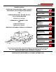
ARMY TM 5-4310-452-14 MARINE CORPS TM 08917A-14 TECHNICAL MANUAL OPERATOR'S, ORGANIZATIONAL, DIRECT SUPPORT, AND GENERAL SUPPORT MAINTENANCE MANUAL FOR COMPRESSOR, ROTARY, AIR, DED, 250 CFM, 100 PSI TRAILER-MOUNTED NSN 4310-01-158-3262 Operating Instructions 2-1 Operator PMCS 2-6 Operator Troubleshooting 3-1 Operator Maintenance Procedures 3-6 Organizational PMCS 4-3 Organizational Troubleshooting 4-9 DS/GS Maintenance 5-1 DS/GS Troubleshooting 5-2 Appendices A-1 COMPONENT OF PNEUMATIC TO
TM 5-4310-452-14 WARNING Carbon monoxide is a colorless, odorless, deadly poisonous gas. Breathing air with carbon monoxide produces symptoms of headache, dizziness, loss of muscular control, a sleepy feeling, and coma. Permanent brain damage or death can result from severe exposure. Carbon monoxide occurs in the exhaust fumes of fuel burning heaters and internal combustion engines and becomes dangerously concentrated under conditions of inadequate ventilation.
TM 5-4310-452-14 WARNING Dry cleaning solvent P-D-680 is toxic and flammable. Always wear protective goggles and gloves, and use only in a well-ventilated area. Avoid contact with skin, eyes, and clothes, and DO NOT breathe vapors. DO NOT use near open flame or excessive heat. The solvent's flash point is 100°F-130°F (38°C-59°C). If you become dizzy while using cleaning solvent, immediately get fresh air and medical help. If solvent contacts eyes, immediately wash your eyes and get medical aid.
TM 5-4310-452-14 WARNING DO NOT interchange the following new 25 lb. Paving Breaker and Tool Components with the older 25 lb. Paving Breaker and Tool Components. Serious injury could result as components of these two Paving Breakers are not interchangeable and do not securely lock in place. • New 25 lb Paving Breaker, NSN 3820-01-195-4167, 7/8 in. hexagon by 31/4 in.
*TM 5-4310-452-14 TM 08917A-I 4 HEADQUARTERS DEPARTMENT OF THE ARMY Washington D. C.
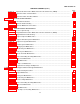
TM 5-4310-452-14 TABLE OF CONTENTS (Con't) Section II. Section III. Operator/Crew Preventive Maintenance Checks and Services (PMCS) .................................. Operation Under Usual Conditions ......................................................................................... Page 2-6 2-15 Section IV. Operation Under Unusual Conditions ..................................................................................... 2-26 CHAPTER 3 OPERATOR MAINTENANCE Section I.
TM 5-4310-452-14 TABLE OF CONTENTS (Con't) Page APPENDIX A References ............................................................................................................................... A-1 APPENDIX B Maintenance Allocation Chart (MAC) ........................................................................................ B-1 APPENDIX C Components Of End Item And Basic Issue Items Lists ..............................................................
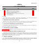
TM 5-4310-452-14 HOW TO USE THIS MANUAL This manual is designed to help maintain the 250 CFM Trailer-Mounted Compressor Unit. This manual describes in detail the Operator's, Organizational, Direct Support, and General Support Maintenance prescribed by the Maintenance Allocation Chart (Appendix B) and Source, Maintenance, and Recoverability (SMR) Codes (TM 5-4310-452-24P).
TM 5-4310-452-14 CHAPTER 1 INTRODUCTION Section I. GENERAL INFORMATION Paragraph Number 1-1 1-2 1-3 1-4 1-5 1-6 1-7 Page Number Title Scope ................................................................................................................................ Maintenance Forms, Records, and Reports ........................................................................ Destruction of Army Material Prevent Enemy Use ..............................................................
TM 5-4310-452-14 1-7. TOOLS AND REPAIR PARTS. a. For authorized common tools and test equipment, refer to the Modified Table of Organization and Equipment (MTOE) applicable to your compressor unit. Repair parts; special tools; test, measurement, and diagnostic equipment (TMDE); and support equipment required to maintain the 250 CFM Trailer-Mounted Compressor Unit are found in TM 54310-452-24P. b. For authorized components of pneumatic tool and compressor outfit, refer to SC 3820-98-CL-E09.
TM 5-4310-452-14 Section II. EQUIPMENT DESCRIPTION Paragraph Number 1-8 1-9 1-10 1-11 Page Number Title Equipment Characteristics, Capabilities, and Features ....................................................... 1-3 Location and Description of Major Components .................................................................. 1-4 Location and Contents of Stencil Markings, Decals, and Plates .......................................... 1-6 Equipment Data ...................................................
TM 5-4310-452-14 1-9. LOCATION AND DESCRIPTION OF MAJOR COMPONENTS. Key 1 2 Component Engine Compressor Description Provides power to drive the compressor. Engine-driven to compress air to 250 cfm (11 cu dm/sec).
TM 5-4310-452-14 1-9. LOCATION AND DESCRIPTION OF MAJOR COMPONENTS (Con't). Key Component 3 4 5 Air Hose Reels Control Panel Indicator Panel 6 7 8 9 Housing Tool Boxes Leveling Jacks Drill Rod Box Description Store air hoses when not in use. Provides the necessary controls to safely operate the engine and compressor. Provides the necessary indicators to safely monitor the operation of the engine and compressor. Reduces noise and protects engine, compressor, and associated components.
TM 5-4310-452-14 1-10. LOCATION AND CONTENTS OF STENCIL MARKINGS, DECALS, AND PLATES. a. The following illustrations show the location and contents of each compressor unit stencil marking, decal, and plate. b. Maintain all stencil markings, decals, and plates so that all information remains legible. If any are missing or no longer legible, replace or repaint.
TM 5-4310-452-14 1-10. LOCATION AND CONTENTS OF STENCIL MARKINGS, DECALS, AND PLATES (Con't).
TM 5-4310-452-14 1-10. LOCATION AND CONTENTS OF STENCIL MARKINGS, DECALS, AND PLATES (Con't).
TM 5-4310-452-14 1-10. LOCATION AND CONTENTS OF STENCIL MARKINGS, DECALS, AND PLATES (Con't).
TM 5-4310-452-14 1-11. EQUIPMENT DATA. COMPRESSOR Manufacturer ...............................................................................................................................Ingersoll-Rand Company Model ................................................................................................................................................. P-250-W-D-M-H268 Output ...........................................................................................................................
TM 5-4310-452-14 Section III. TECHNICAL PRINCIPLES OF OPERATION Paragraph Number 1-12 1-13 1-14 1-15 1-16 Title Page Number General............................................................................................................................... 1-11 Engine ............................................................................................................................... 1-12 Fuel System .............................................................................................
TM 5-4310-452-14 1-12. GENERAL (Con't). 3. Fuel Tank Filler Cap 4. Air Cleaner Assembly 5. Restriction Indicator B. Exhaust Pipe 7. 01 Cooler Fan 8. ON Filter Assembly 9. Housing 10. ON Separator 11. ON Temperature Bypass 12. Muffler 13. Automatic Blowdown Valve 14. Starter Motor and Solenoid 15. Slave Receptacle 16. Alternator 17. Storage Batteries 18. Minimum Pressure and Service Valve 19. Belt Break Switch 20. Fuel Tank 21. Engine Cooing Blower 1-13. ENGINE. a.
TM 5-4310-452-14 1-13. ENGINE (Con't). (4) Exhaust Stroke. As the piston moves upward on the fourth stroke, it forces the burned and expanded gases from the cylinder through the open exhaust valve, which closes just before the piston reaches top dead center. The air inlet valve opens and the cycles are repeated (i. e., there are two down and two up strokes in the cycle). c. The following illustration shows the location of the major engine components. 1. Rocker Chamber Cover 2. Injection Line 3.
TM 5-4310-452-14 1-14. FUEL SYSTEM (Con't). 1. Injector 2. Fuel Filter 3. Injection Pump 4. Solenoid Valve 5. Metering Fuel Pump 6. Fuel/Water Separator 1-15. AIR COMPRESSOR. a. The air compressor is an enclosed helical, single stage, positive displacement-type. b. Air is compressed when two oil-flooded helical rotors (male and female) on parallel shafts mesh in an enclosed housing with air inlet and outlet ports located on opposite ends of the housing.
TM 5-4310-452-14 1-15. AIR COMPRESSOR (Con't). c. Air flow through the compressor can be regulated from full capacity to zero capacity depending on the demand placed on the unit. Reduction to zero capacity is done by the air inlet unloader valve.
TM 5-4310-452-14 1-16. LUBRICATION SYSTEM. Components of the compressor unit's air and oil flow.
TM 5-4310-452-14 1-16. LUBRICATION SYSTEM (Con't). Key Component 1 Inlet Air Cleaner 2 Air Actuating Governor Control Compressor 3 4 5 Unloader Valve Assembly Oil Cooler 6 Oil Temperature Bypass Valve 7 8 Oil Filter Assembly Manual Blowdown Valve 9 Safety Relief Valve 10 Oil Separator 11 Automatic Blowdown Valve Regulating Valve 12 13 Minimum Pressure and Service Valve Description Prevents foreign particles such as dirt and water from being inducted into the compressor air inlet.
TM 5-4310-452-14 1-16. LUBRICATION SYSTEM (Con't).
TM 5-4310-452-14 1-16. LUBRICATION SYSTEM (Con't). Key Component 14 Service-Air Valve 15 Discharge Pressure Gage Description A two-way valve that reduces load requirements on the engine during start-up, thereby permitting engine warm-up before loading the compressor to full capacity. Located in the indicator panel to identify air pressure in the oil separator system. Normal reading should be 80-120 psi (552-827 kPa), depending on the speed and pressure regulator adjustment.
TM 5-4310-452-14 CHAPTER 2 OPERATING INSTRUCTIONS Section I. DESCRIPTION AND USE OF OPERATOR'S CONTROLS AND INDICATORS Paragraph Number 2-1 2-2 Page Number Title General .............................................................................................................................. 2-1 Controls and Indicators........................................................................................................ 2-2 2-1. GENERAL.
TM 5-4310-452-14 2-2. CONTROLS AND INDICATORS. Key Component 1 Discharge Pressure 2 Tach/Hourmeter 3 Engine Oil Pressure 4 5 6 Fuel Pressure Fuel Level Ammeter 7 Compressor Oil Temp Description Indicates the pressure of air leaving the compressor. Should be 80-120 psi (552-827 kPa). The tachometer portion indicates the engine speed in revolutions per minute (rpm). The hourmeter portion of this gage indicates and records the total number of hours of actual operation.
TM 5-4310-452-14 2-2. Key CONTROLS AND INDICATORS (Con't). Component 8 Service-air/Push After Warm Up 9 10 11 12 13 Pull To Stop Ether Inject Start Safety Circuit Bypass Light On/Off Switch Description This button controls the service air valve and allows the engine to warm up with a minimum load. This button should be pressed only after the engine is warm. The valve will reset automatically when the engine is turned off. Stops the engine when pulled.
TM 5-4310-452-14 2-2. Key CONTROLS AND INDICATORS (Con't). Component 14 Manual Blowdown Valve 15 Compressor Oil Level Sight Tube Key 16 Description Relieves pressure on the oil separator system when the unit is shut down. Usually, this valve will only be used if the automatic blowdown valve fails to operate normally. Indicates level of oil in compressor. Oil level must be present in sight tube before operating compressor unit.
TM 5-4310-452-14 2-2. CONTROLS AND INDICATORS (Con't). Key 17 18 Component Manifold Valves Service Air Manifold Drain Description Provide additional hookups and controls for more air hoses. Removes built-up moisture in service air manifold.
TM 5-4310-452-14 Section II. OPERATOR PREVENTIVE MAINTENANCE CHECKS AND SERVICES (PMCS) Paragraph Number 2-3 2-4 2-5 2-6 2-7 2-8 2-9 Table 2-1 Title Page Number General .............................................................................................................................. Intervals ............................................................................................................................. Reporting Repairs ...........................................................
TM 5-4310-452-14 2-6. GENERAL PMCS PROCEDURES (Con't). (4) An item is ADEQUATELY Lubricated if it has been lubricated in accordance with LO 5-4310-452-12 (5) An item is WORN if there is too much play between joining parts, if an item does not meet the wear specifications provided, or when WARNING, CAUTION, and data stencil markings, plates, or decals are not legible. (6) For LEAKAGE definitions, see paragraph 2-9. b.
TM 5-4310-452-14 2-8. CLEANING AGENTS (Con't). b. Keep excess lubricants away from exterior parts that do not require lubrication. c. Use only those authorized cleaning solvents or agents listed in Appendix E. WARNING Dry cleaning solvent P-D-680 is toxic and flammable. Always wear protective goggles and gloves, and use only in a well-ventilated area, Avoid contact with skin, eyes, and clothes, and DO NOT breathe vapors. DO NOT use near open flame or excessive heat.
TM 5-4310-452-14 Table 2-1. Operator Preventive Maintenance Checks and Services (PMCS). B-Before D-During Interval Item No. B D A W • • a. b. • 1 VEHICLE EXTERIOR a. Check for fluid leakage or appearance of fluid leakage, b. Visually check for damaged piping or hoses, and loose, missing, or damaged parts. damaged. c. Operate lights. d. Leveling jacks operate properly. If leveling jacks are missing or damaged, notify your supervisor.
TM 5-4310-452-14 Table 2-1. Operator Preventive Maintenance Checks and Services (PMCS) (Con't). B-Before D-During Interval Item No. B 5 D A W A-After ITEM TO BE INSPECTED PROCEDURE: Check for and have repaired filled or adjusted as needed W-Weekly Equipment is Not Ready Available If: ENGINE CRANKCASE CAUTION To prevent engine damage, engine oil level should be checked twice daily until engine exceeds 200 hours of operation. NOTE Compressor unit must be level to perform this check.
TM 5-4310-452-14 Table 2-1. Operator Preventive Maintenance Checks and Services (PMCS) (Con't). B-Before D-During Interval Item No. B D 10 A W A-After ITEM TO BE INSPECTED PROCEDURE: Check for and have repaired filled or adjusted as needed W-Weekly Equipment is Not Ready Available If: COMPRESSOR OIL LEVEL WARNING Compressor lubrication/cooling system is under pressure.
TM 5-4310-452-14 Table 2-1. Operator Preventive Maintenance Checks and Services (PMCS) (Con't). B-Before D-During Interval Item No. B D A W 12 13 14 A-After ITEM TO BE INSPECTED PROCEDURE: Check for and have repaired filled or adjusted as needed INSTRUMENTS AND GAGES Check for proper indication and operation.
TM 5-4310-452-14 Table 2-1. Operator Preventive Maintenance Checks and Services (PMCS) (Con't). B-Before D-During Interval Item No. 15 B D A W • A-After ITEM TO BE INSPECTED PROCEDURE: Check for and have repaired filled or adjusted as needed W-Weekly Equipment is Not Ready Available If: ENGINE THROTTLE CONTROL Lubricate rod end bearing (6) with grease (Item 5, Appendix E). Lubricate linkage points (7 and 8) with engine oil (Item 8, Appendix E).
TM 5-4310-452-14 Table 2-1. Operator Preventive Maintenance Checks and Services (PMCS) (Con't). B-Before D-During Interval Item No. 1 B D A W A-After ITEM TO BE INSPECTED PROCEDURE: Check for and have repaired filled or adjusted as needed W-Weekly Equipment is Not Ready Available If: UNLOADER VALVE ASSEMBLY WARNING Unloader valve assembly may be under pressure. Protect eyes and skin from unloader draincock opening during draining procedure.
TM 5-4310-452-14 Section III. OPERATION UNDER USUAL CONDITIONS Paragraph Number 2-10 2-11 2-12 2-13 2-14 2-15 2-16 Title Page Number General .............................................................................................................................. 2-15 Preparation for Use ............................................................................................................ 2-15 Starting Under Usual Conditions .....................................................................
TM 5-4310-452-14 2-12. STARTING UNDER USUAL CONDITIONS (Con't). CAUTION Do not operate the compressor unit more than 15°out-of-level, either end-to-end or side-to-side. If the unit is not level, the engine oil will not circulate correctly and may result in severe engine damage. b. Raise or lower front leveling jack (3) until compressor unit (2) is within 15° of level, end-to-end. If compressor unit is not within 15°of level, side-to-side, move compressor unit to a more suitable site.
TM 5-4310-452-14 2-12. STARTING UNDER USUAL CONDITIONS (Con't). CAUTION All service air valves must be closed to allow system to build up enough air pressure to lubricate compressor. d. Close and secure all service and hose reel valves (5), e. Completely push in manual stop handle (7). CAUTION Do not operate starting motor more than 30 seconds at a time. Allow starting motor to cool approximately 2 minutes between starting attempts. f.
TM 5-4310-452-14 2-12. STARTING UNDER USUAL CONDITIONS (Con't). g. When engine starts, release only the START button (9). Continue to press SAFETY CIRCUIT BYPASS button (10) until DISCHARGE PRESSURE gage (11) on indicator panel (12) reaches 40 psi (276 kPa), then release SAFETY CIRCUIT BYPASS button. h. When DISCHARGE PRESSURE gage (11) reaches approximately 50 psi (345 kPa) and engine is warm, press SERVICE-AIR button (6).
TM 5-4310-452-14 2-13. STOPPING THE UNIT (Con't). WARNING Slowly open manual blowdown valve, being careful to keep face and any bare skin away from valve opening. If this warning is not followed, injury to personnel may result. CAUTION Never allow unit to sit idle with pressure in oil separator system. If compressor is started with a charged air system, damage to compressor components could result. c.
TM 5-4310-452-14 2-14. DURING OPERATION. a. Perform all During (D) PMCS. Become familiar with the normal operation of the compressor unit and with the readings on the indicators, Damage to the equipment, expensive repairs, and downtime can be avoided by an alert operator who can detect a problem in its early stages and help organizational maintenance correct it before it becomes a more serious problem. CAUTION Care must be taken to prevent air in fuel system. Never allow fuel tank to run dry.
TM 5-4310-452-14 2-15. COUPLING UNIT TO TOWING VEHICLE (Con't). NOTE Use front leveling jack to raise or lower drawbar as required. b. Position towing vehicle so pintle is lined up under drawbar (4). c. Raise front leveling jack (5) with handcrank (3) until the drawbar (4) is seated in towing vehicle pintle and front leveling jack clears ground, d. Remove locking pin (1) and fold up front leveling jack (5) to travel position, Insert locking pin to lock leveling jack.
TM 5-4310-452-14 2-15. COUPLING UNIT TO TOWING VEHICLE (Con't). h. Remove chocks (12) from trailer wheels and store in retaining straps. Attach tie-down straps (13) to hold chocks in place. i. Release parking brake (14). WARNING • DO NOT tow compressor unit faster than 55 mph (88 kph) over paved highways, 10 mph (16 kph) over graded gravel roads or 8 mph (13 kph) over rough cross-country terrain or Injury to personnel may result.
TM 5-4310-452-14 2-16. UNCOUPLING UNIT FROM TOWING VEHICLE (Con't). c. Disconnect electrical power cable (5) and place in holder (7). d. Disconnect service and emergency brake air lines (4) from towing vehicle, and place in dummy couplers (9). Pull air tank drain cable (6) to discharge water from air tank. e. Disconnect safety chains (10) from towing vehicle and hook to front crossmember hook (8). f. Remove locking pin (11) and swing down front leveling jack (12).
TM 5-4310-452-14 2-16. UNCOUPLING UNIT FROM TOWING VEHICLE (Con't). g. Using front leveling jack (12), raise drawbar (14) out of pintle (13). h. Move towing vehicle away from compressor unit (see TM 9-2320-272-10).
TM 5-4310-452-14 2-16. UNCOUPLING UNIT FROM TOWING VEHICLE (Con't). i. Using front leveling jack (12), raise or lower trailer until compressor unit is within 15° of level, end-to-end. If compressor unit is not within 15° of level, side-to-side, move compressor unit to a more suitable site (see paragraph 215). j. Remove locking pins (16) and swing down rear leveling jacks (15). Insert locking pins to lock rear leveling jacks in position. Lower rear leveling jacks until firm contact is made with the ground.
TM 5-4310-452-14 Section IV. OPERATION UNDER UNUSUAL CONDITIONS Paragraph Number 2-17 2-18 2-19 2-20 2-21 2-22 2-23 2-24 Title Page Number General .............................................................................................................................. 2-26 Operation in Dusty or Sandy Areas, or Extreme Dry Heat ................................................... 2-26 Operation in Extreme Heat and High Humidity ...................................................................
TM 5-4310-452-14 2-19. OPERATION IN EXTREME HEAT AND HIGH HUMIDITY (Con't). e. Ensure that cooling fins and cooling fans are kept clean and unobstructed (see paragraph 3-5). f. Occasionally drain service air manifold during the shift; drain more often if necessary. 2-20. OPERATION IN EXTREME COLD, SNOW, OR MUD. a. General. (1) Keep the unit clean and free of snow and mud accumulations. (2) Do not allow snow or mud to get inside housing. If it does, clean thoroughly.
TM 5-4310-452-14 2-20. OPERATION IN EXTREME COLD, SNOW, OR MUD (Con't). (3) Open manual blowdown valve (2) and service valve (3). NOTE When using ETHER INJECT knob, ensure that knob is pushed in immediately after pulling it out. (4) Pull ETHER INJECT knob (5) once, and then completely push it back in. Simultaneously push SAFETY CIRCUIT BYPASS (7) and START (6) buttons. Release START button when engine starts, Release SAFETY CIRCUIT BYPASS button when engine oil pressure reaches 20 psi (138 kPa).
TM 5-4310-452-14 2-20. OPERATION IN EXTREME COLD, SNOW, OR MUD (Con't). c. Jump Starting Engine with Slave Receptacle. NOTE Be aware that in extremely cold weather, cranking power of storage batteries can be reduced by 50% or more. In extremely cold weather, it is advisable to remove storage batteries from unit and store them In a warm room until needed. (1) Connect slave power cable (9) to slave connection of starting source. (2) Connect slave power cable (9) to slave receptacle (8) of compressor unit.
TM 5-4310-452-14 2-21. OPERATION IN SALT AIR AND SEA SPRAY. a. Operations in salt air and sea spray can be damaging to the unit because of saltwater's corrosive effects. Be particularly aware of the potential for rust. b. Check twice daily for water in the oil of both the engine and the compressor. c. Drain the fuel/water separator whenever water is visible in the sightbowl (see paragraph 3-6). d. Keep the engine throttle control cylinder rod clean and free of rust. 2-22. OPERATION AT HIGH ALTITUDES. a.
TM 5-4310-452-14 2-24. EMERGENCY OPERATIONS. a. In an emergency, the unit can be operated with damaged running gear. b. If the compressor, engine, or related assemblies are damaged, the unit CANNOT be operated.
TM 5-4310-452-14 CHAPTER 3 OPERATOR MAINTENANCE Section I. LUBRICATION INSTRUCTIONS 3-1. OPERATOR LUBRICATION INSTRUCTIONS. For specific lubrication points on the 250 CFM Trailer-Mounted Compressor Unit, refer to LO 5-4310-452-12. Section II. OPERATOR TROUBLESHOOTING Paragraph Number Page Number Title 3-2 General .............................................................................................................................. 3-1 3-3 Troubleshooting Symptom Index ...........................
TM 5-4310-452-14 3-3. TROUBLESHOOTING SYMPTOM INDEX. Troubleshooting Procedure Page COMPRESSOR Air discharge capacity too low ......................................................................................................... Oil: Consumption too high .................................................................................................................. Excessive carry-over at air discharge ...........................................................................................
TM 5-4310-452-14 Table 3-1. Operator Troubleshooting Procedures (Con't). MALFUNCTION TEST OR INSPECTION CORRECTIVE ACTION 2. ENGINE IS DIFFICULT TO START. Step 1. Check for loose, dirty, or corroded battery terminals. If battery terminals are loose, dirty, or corroded, notify your supervisor. Step 2. Check engine air cleaner restriction indicator. If red condition is present, clean air cleaner (see paragraph 3-4). Step 3. Check that engine oil is proper grade (cold weather).
TM 5-4310-452-14 Table 3-1. Operator Troubleshooting Procedures (Con't). MALFUNCTION TEST OR INSPECTION CORRECTIVE ACTION Step 3. Ensure that compressor unit is level, Adjust compressor unit to within 15°of level end-to-end (see paragraph 2-12). 6. ENGINE RUNS BACKWARD WHEN TURNED OFF. Check engine idle speed on TACH/HOURMETER gage. If engine idle speed is greater than 1400 rpm, notify your supervisor. COMPRESSOR 7. EXCESSIVE OIL CARRY-OVER AT AIR DISCHARGE, Check oil level in oil separator sight tube.
TM 5-4310-452-14 Table 3-1. Operator Troubleshooting Procedures (Con't). MALFUNCTION TEST OR INSPECTION CORRECTIVE ACTION 10. OIL CONSUMPTION TOO HIGH. Check to see if compressor unit is level. Adjust compressor unit to within 15°of level end-to-end (see paragraph 2-12). 11. OIL LEVEL READING ERRATIC. Check to see if compressor unit is level. Adjust compressor unit to within 15°of level end-to-end (see paragraph 2-12).
TM 5-4310-452-14 Section III. OPERATOR MAINTENANCE PROCEDURES Paragraph Number 3-4 3-5 3-6 3-7 3-8 Page Number Title Air Cleaner Cleaning .......................................................................................................... 3-6 Engine Cooling Fan, Cooling Fins, and Oil Cooler Cleaning ............................................... 3-7 Fuel/Water Separator Servicing .........................................................................................
TM 5-4310-452-14 3-4. AIR CLEANER CLEANING (Con't). c. Installation. (1) Place filter element (5) in air cleaner body (3) and install wingnut (6). (2) Install cover (7) on air cleaner body (3). Install wingnut (2) fingertight. (3) Press down on top of restriction indicator (4) and reset to green condition. (4) Close left and right door assemblies (1). 3-5. ENGINE COOLING FAN, COOLING FINS, AND OIL COOLER CLEANING. a. Open left door assembly (1). b.
TM 5-4310-452-14 3-5. ENGINE COOLING FAN, COOLING FINS, AND OIL COOLER CLEANING (Con't). WARNING Compressed air used for cleaning or drying purposes, or for clearing restrictions, should never exceed 30 psi (207 kPa). Wear protective clothing (goggles/shield, gloves, etc.) and use caution to avoid injury to personnel. CAUTION When using a wire brush during cleaning, ensure that cooling fins and oil cooler are not damaged.
TM 5-4310-452-14 3-6. FUEL/WATER SEPARATOR SERVICING. NOTE Drain fuel/water separator only when water Is visible in sightbowl. a. Open left door assembly (1). b. Place suitable container under trailer at bottom end of hose (6). c. Loosen drain assembly knob (5) and drain water from fuel/water separator (3) until only clear fuel is draining. d. Tighten drain assembly knob (5) and unscrew hand primer pump knob (2). e.
TM 5-4310-452-14 3-8. PARKING BRAKE ADJUSTMENT. a. Place parking brake handle (1) in released position. b. Turn parking brake handle knob (2) clockwise to tighten, or counterclockwise to loosen parking brake. c. Place parking brake handle (1) in engaged position, then in released position to test.
TM 5-4310-452-14 CHAPTER 4 ORGANIZATIONAL MAINTENANCE Section I. SERVICE UPON RECEIPT Paragraph Number 4-1 4-2 4-3 Page Number Title Preparation for Use ............................................................................................................ 4-1 Lubrication .......................................................................................................................... 4-2 Servicing instructions ................................................................................
TM 5-4310-452-14 4-1. PREPARATION FOR USE (Con't). (4) Raise unit off carrier with lifting device and set unit down on flat, level surface. c. Inspection of the Unit. (1) Check carefully for and report any and all damage. (2) Refer to the bill of lading and ensure that the unit has everything listed. (3) Check tires for proper inflation (see Table 2-1). 4-2. LUBRICATION.
TM 5-4310-452-14 Section II. ORGANIZATIONAL PREVENTIVE MAINTENANCE CHECKS AND SERVICES (PMCS) Paragraph Number Page Number Title 4-4 General .............................................................................................................................. 4-5 Intervals ............................................................................................................................. 4-6 Reporting Repairs ...............................................................................
TM 5-4310-452-14 4-7. GENERAL PMCS PROCEDURES (Con't). (6) For a classification of LEAKAGE, see paragraph 2-9. b. Perform inspections of welds, electrical conduits, tubing, and hoses as described below: (1) Check for loose or chipped paint, rust, or gaps where parts are welded together, If a bad weld is found, notify your supervisor. (2) Look for cracked, frayed, loose, or broken electrical conduits, tubing, and hoses. components. Repair or report unserviceable items.
TM 5-4310-452-14 Table 4-1. Organizational Preventive Maintenance Checks and Services (PMCS). Q-Quarterly M - Monthly H-Hours INTERVAL ITEM NO. ITEM TO BE INSPECTED. Q S PROCEDURES H WARNING The compressor lubricating/cooling system is under pressure. To prevent injury, do not, under any circumstance, remove drain plug or filler plug from the compressor lubricating/cooling system while under pressure. Open the manual blowdown valve as a safety precaution first. NOTE Perform all Operator PMCS first.
TM 5-4310-452-14 Table 4-1. Organizational Preventive Maintenance Checks and Semites (PMCS) (Con't). Q-Quarterly M - Monthly H-Hours INTERVAL ITEM NO. ITEM TO BE INSPECTED. Q S PROCEDURES H 4 COMPRESSOR WARNING The compressor lubricating/cooling system is under pressure, To prevent injury, do not, under any circumstance, remove drain plug or filler plug from the compressor lubricating/cooling system while under pressure. Open the manual blowdown valve as a safety precaution first. 250 a.
TM 5-4310-452-14 Table 4-1. Organizational Preventive Maintenance Checks and Services (PMCS) (Con't). Q - Quarterly S - Semiannual H - Hours INTERVAL ITEM NO. ITEM TO BE INSPECTED Q S 10 AIR SILENCER • 11 PROCEDURES H Remove, clean, and inspect air silencer (see paragraph 4-94). • DRAWBAR Check drawbar mounting bolts for proper torque of 180-200 lb. -ft (244-271 N*m).
TM 5-4310-452-14 Section III. ORGANIZATIONAL TROUBLESHOOTING Paragraph Number 4-9 4-10 Table 4-2 Table 4-3 Title Page Number General................................................................................................................................... 4-9 Troubleshooting Symptom Index............................................................................................. 4-10 Mechanical Troubleshooting Procedures ..........................................................................
TM 5-4310-452-14 4-10. TROUBLESHOOTING SYMPTOM INDEX. Troubleshooting Procedure Page MECHANICAL TROUBLESHOOTING COMPRESSOR Air discharge pressure too low.................................................................................................... Blowdown valve operates erratically........................................................................................... Compressor air unsuitable for sandblasting (excessive oil in air outlet).......................................
TM 5-4310-452-14 Table 4-2. Mechanical Troubleshooting Procedures. MALFUNCTION TEST OR INSPECTION CORRECTIVE ACTION ENGINE 1. WILL NOT START. Check to see if fuel filter is clogged. Replace fuel filter element (see paragraph 4-26). 2. DIFFICULT TO START/PERFORMS POORLY. Step 1. Check to see if fuel is forming wax (winter operation). Replace with winter-grade fuel (see paragraph 2-20). Step 2. Check for erratic or insufficient fuel supply. Bleed fuel system (see paragraph 4-21). Step 3.
TM 5-4310-452-14 Table 4-2. Mechanical Troubleshooting Procedures (Con't). MALFUNCTION TEST OR INSPECTION CORRECTIVE ACTION 6. SURGES WHEN RUNNING. Step 1. Check to see if regulating valve is restricted. Replace regulating valve (see paragraph 4-94). Step 2. Check for tension on engine speed control inner spring. Adjust throttle control (see paragraph 4-25). Step 3. Check to see if engine speed control springs are broken, Replace throttle control (see paragraph 4-25). 7. WILL NOT RUN AT CORRECT SPEED.
TM 5-4310-452-14 Table 4-2. Mechanical Troubleshooting Procedures (Con't). MALFUNCTION TEST OR INSPECTION CORRECTIVE ACTION Step 3. Check for defective minimum pressure and service valve. Repair or replace minimum pressure and service valve (see paragraph 4-100). Step 4. Check to see if unit was shut down improperly, Instruct operator on correct shutdown procedure. 3. AIR DISCHARGE PRESSURE TOO LOW. Step 1. Check to see if engine speed is too low. Adjust throttle control (see paragraph 4-25). Step 2.
TM 5-4310-452-14 Table 4-2. Mechanical Troubleshooting Procedures (Con't). MALFUNCTION TEST OR INSPECTION CORRECTIVE ACTION 7. UNIT WILL NOT UNLOAD. Step 1. Check for blocked regulating valve inlet. Remove and clean regulating valve (see paragraph 4-94). Step 2. Check regulating valve adjustment. Adjust throttle control (see paragraph 4-25). Step 3. Check for defective blowdown valve. Replace blowdown valve (see paragraph 4-95). 8. SAFETY RELIEF VALVE RELIEVES. Step 1. Check to see if safety valve pops off.
TM 5-4310-452-14 Table 4-3. Electrical Troubleshooting Procedures. MALFUNCTION TEST OR INSPECTION CORRECTIVE ACTION 1. ENGINE WILL NOT CRANK. NOTE • Ensure that batteries are fully charged. • Ensure that cables are good and correctly installed. • Ensure that connectors are clean and secure on terminals. Step 1. Check starter circuit fuse. If bad, replace fuse (see paragraph 4-40). If OK, go step 2. NOTE • When testing for voltage, negative lead from multimeter should be to ground (trailer frame).
TM 5-4310-452-14 Table 4-3. Electrical Troubleshooting Procedures (Con't). MALFUNCTION TEST OR INSPECTION CORRECTIVE ACTION Step 2. Check battery cables for proper size, freedom of corrosion, and proper installation. If NOT OK, repair or replace wiring harness (see paragraph 4-63). If OK, go to step 3. NOTE If ambient temperature is below 32 o F (0°C) check that engine oil and diesel fuel ratings are correct. Step 3. Test current draw of starter motor, If NOT OK, replace starter (see paragraph 4-39).
TM 5-4310-452-14 Table 4-3. Electrical Troubleshooting Procedures (Con't). MALFUNCTION TEST OR INSPECTION CORRECTIVE ACTION Step 2. Was charging system operating time limited? If OK, go to step 3. If NOT OK, charge batteries as necessary (see TM 9-6140-200-14). Start engine to verify malfunction has been corrected. Step 3. Check for loose, dirty, or corroded terminals, leads, plugs, or connectors. If OK, go to step 4.
TM 5-4310-452-14 Section IV. ENGINE COMPONENT MAINTENANCE Paragraph Number 4-11 4-12 4-13 4-14 4-15 4-16 Title Flywheel Inspection................................................................................................................. Valve Cover Replacement ...................................................................................................... Valve Clearance Adjustment ...................................................................................................
TM 5-4310-452-14 4-11. FLYWHEEL INSPECTION (Con't). NOTE Steps 4 and 5 must be performed at the same time. 4. Turn crankshaft pulley (10) counterclockwise one complete revolution with 36 mm socket and breaker bar. 5. Inspect flywheel (3), through access hole (2) in flywheel housing (4), for cracks, chips, or broken gear teeth. If damaged, notify your supervisor. 6. Install cover (5) on flywheel housing (4), Install 2 bolts (7), new lockwashers (6), 2 bolts (9), new lockwashers (8), and clamps (1).
TM 5-4310-452-14 4-12. VALVE COVER REPLACEMENT. This Task Covers: a. Removal b. Installation Initial Setup: Equipment Conditions: • Engine off. • Left and right door assemblies open. Tools/Test Equipment: • General mechanic's tool kit Materials/Parts: • Sealing compound (Item 12, Appendix E) • One gasket • One shouldered washer a. REMOVAL 1. Remove bolt (1), washer (2), and shouldered washer (3) from cover (4). Discard shouldered washer.
TM 5-4310-452-14 4-13. VALVE CLEARANCE ADJUSTMENT. This Task Covers: Adjustment Initial Setup: Equipment Conditions: • Engine off and cool. • Left and right door assemblies open. • Battery cables disconnected (see paragraph 4-57). • Valve covers removed (see paragraph 4-12). Tools/Test Equipment: •·General mechanic's tool kit • Feeler gage ADJUSTMENT NOTE To obtain accurate clearance reading, ensure that engine Is cool during valve clearance adjustment. 1.
TM 5-4310-452-14 4-13. VALVE CLEARANCE ADJUSTMENT (Con't). 3. Loosen locknut (3) on rocker arm (5), Insert 0.15 mm (0.006 in.) feeler gage between rocker arm and top of valve stem (6). Turn setscrew (4) until a slight drag can be felt on feeler gage. 4. Tighten locknut (3) and check valve clearance. Repeat step 3 if necessary. 5. Turn crankshaft pulley (1) counterclockwise (direction of rotation) one complete revolution (360°from position 1). 6.
TM 5-4310-452-14 4-14. EXHAUST MANIFOLD REPLACEMENT. This Task Covers: a. Removal b. Inspection c. Installation Initial Setup: Equipment Conditions: Tools/Test Equipment : • Engine off and cool. • General mechanic's tool kit • Left and right door assemblies open. Materials/Parts: • Muffler and pipes removed (see paragraph 4-31). •·Four gaskets a. REMOVAL 1. Remove B nuts (1) from studs (3) in cylinder heads. 2. Remove exhaust manifold (4) from studs (3).
TM 5-4310-452-14 4-15. INTAKE MANIFOLD REPLACEMENT. This Task Covers: a. Removal b. Inspection c. Installation Initial Setup: Equipment Conditions: Materials/Parts: • Engine off and cool. • Four gaskets • Left and right door assemblies open. • Muffler and pipes removed (see paragraph 4-31). Tools/Test Equipment: • General mechanic's tool kit a. REMOVAL 1. Loosen clamp (1) and remove air intake hose (2) from intake manifold (3). 2. Remove engine starting aid line (8) from intake manifold (3). 3.
TM 5-4310-452-14 4-16. ENGINE AIR CLEANER ASSEMBLY REPLACEMENT. This Task Covers: a. Removal b. Installation Initial Setup: Equipment Conditions: • Engine off. • Left and right door assemblies open. • Engine air cleaner filter element removed (see paragraph 3-4). Materials/Parts: • Two lockwashers Tools/Test Equipment: • General mechanic's tool kit a. REMOVAL 1. Loosen 2 clamps (4) on hose (5). Remove hose and clamps from air cleaner body (8) and intake manifold (6).
TM 5-4310-452-14 4-16. ENGINE AIR CLEANER ASSEMBLY REPLACEMENT (Con't). 3. Remove restriction indicator (7) from air cleaner body (8). 4. Remove 4 nuts (2) and capscrews (12) from bracket (1). 5. Remove 2 bolts (14) and lockwashers (13) from bracket (1) and unloader valve assembly (3). Discard lockwashers. 6. Remove bracket (1). b. INSTALLATION 1. Position bracket (1) on unloader valve assembly (3). Install 2 bolts (14) and new lockwashers (13) in bracket. Tighten bolts to 58 lb.-ft. (78 N•m). 2.
TM 5-4310-452-14 Section V. ENGINE LUBRICATION SYSTEM MAINTENANCE Paragraph Number 4-17 4-18 4-19 4-20 Page Number Title Oil Cooler Replacement ......................................................................................................... Engine Oil Filter Element Replacement .................................................................................. Oil Filter Base Assembly Replacement ..................................................................................
TM 5-4310-452-14 4-17. OIL COOLER REPLACEMENT (Con't). FOLLOW-ON TASKS: • Install cooling duct and stay plate (see paragraph 4-34). • Start unit and check for leaks (see paragraph 2-12). • Close left door assembly.
TM 5-4310-452-14 4-18. ENGINE OIL FILTER ELEMENT REPLACEMENT. This Task Covers: a. Removal b. Installation Initial Setup: Equipment Conditions: Materials/Parts: • Engine off. • Dry cleaning solvent (Item 3, Appendix E) • Left door assembly open.
TM 5-4310-452-14 4-18. ENGINE OIL FILTER ELEMENT REPLACEMENT (Con't). b. INSTALLATION 1. Apply a thin film of new oil on new oil filter gasket (3). CAUTION Do not overtighten oil filter element. Overtightening oil filter element can cause oil to leak and result in severe engine damage. 2. Screw new oil filter element (2) in place on filter base assembly (1) until oil filter gasket (3) contacts filter base assembly. Tighten oil filter element 3/4turn more with filter strap wrench.
TM 5-4310-452-14 4-19. OIL FILTER BASE ASSEMBLY REPLACEMENT. This Task Covers: a. Removal b. Installation Initial Setup: Equipment Conditions: Materials/Parts: • Engine off. • Sealing compound (Item 12, Appendix E) • Left door assembly open. • One gasket • Engine oil filter element removed (see para• Five copper washers graph 4-18). • Fuel filter element removed (see paragraph 4-26). Tools/Test Equipment: General mechanic's tool kit a. REMOVAL 1.
TM 5-4310-452-14 4-19. OIL FILTER BASE ASSEMBLY REPLACEMENT (Con't). b. INSTALLATION 1. 2. 3. 4. 5. Install tee (5), elbow (6), and restrictor (7) on filter base assembly (3). Apply sealing compound on new gasket (4). Position gasket on filter base assembly (3). Position filter base assembly (3) and gasket (4) and install 2 bolts (13) and washers (12). Install oil line (8) on tee (5).
TM 5-4310-452-14 4-20. OIL LINE REPLACEMENT. This Task Covers: a. Removal b. Installation Initial Setup: Equipment Conditions: • Engine off. • Left door assembly open. • Oil filter base assembly removed (see paragraph 4-19). graph 4-19). • Oil cooler removed (see paragraph 4-17). • Metering fuel pump removed (see paragraph 4-22). Materials/Parts: • Four copper washers Tools/Test Equipment: • General mechanic's tool kit a. REMOVAL 1.
TM 5-4310-452-14 Section VI. ENGINE FUEL SYSTEM MAINTENANCE Paragraph Number 4-21 4-22 4-23 4-24 4-25 4-26 4-27 4-28 4-29 Title Fuel System Bleeding ............................................................................................................ Metering Fuel Pump Maintenance .......................................................................................... Fuel Tank Maintenance ..........................................................................................................
TM 5-4310-452-14 4-21. FUEL SYSTEM BLEEDING (Con't). NOTE When bleeding the fuel system, you are actually moving the fuel pump by hand. If no resistance is felt when pumping the fuel pump priming lever, perform step 2 until resistance is felt. If resistance is felt, go to step 3. 2. Turn crankshaft pulley (5) clockwise, in 1/4-turn increments, with 36 mm socket and breaker bar until resistance is felt on priming lever (4). 3.
TM 5-4310-452-14 4-22. METERING FUEL PUMP MAINTENANCE. This Task Covers: a. Removal b. Disassembly c. Assembly d. Installation Initial Setup: Equipment Conditions: Materials/Parts: • Engine off. • Dry cleaning solvent (Item 3, Appendix E) • Left door assembly open. • Rag (Item 11, Appendix E) • Left door assembly open.
TM 5-4310-452-14 4-22. METERING FUEL PUMP MAINTENANCE (CON'T). a. REMOVAL 1. Remove fluid passage bolt (5), 3 washers (4), and 2 hoses (6) from metering fuel pump (3). NOTE Fluid passage bolt internal check valve. includes an 2. Remove fluid passage bolt (8), 3 washers (7), and 2 hoses (9) from metering fuel pump (3). 3. Remove 3 nuts (10) and lockwashers (11) from metering fuel pump (3). Remove metering fuel pump and gasket (2) from injection pump drive assembly (1). Discard gasket and lockwashers.
TM 5-4310-452-14 4-22. METERING FUEL PUMP MAINTENANCE (CON'T). 4. Inspect strainer (16) for cracks or breaks. Replace strainer if damaged. c. ASSEMBLY 1. Position strainer (16), new preformed packing (15), and cover (14) on metering fuel pump (3). 2. Install capscrew (12) and washer (13) in metering fuel pump (3). d. INSTALLATION 1. Position new gasket (2) and metering fuel pump (3) on injection pump drive assembly (1). Install 3 nuts (10) and new lockwashers (11).
TM 5-4310-452-14 4-23. FUEL TANK MAINTENANCE. This Task Covers: a. Removal b. Disassembly c. Assembly d. Installation Initial Setup: Equipment Conditions: • Engine off. • Left door assembly open. • Fuel tank drained (see LO 5-4310-452-12). • Fuel/water separator removed from baffle (see Materiels/Parts: • One filler opening cap Tools/Test Equipment: • General mechanic's tool kit • paragraph 4-27). Personnel Required: Two a. REMOVAL 1. 2. 3. 4. 5.
TM 5-4310-452-14 4-23. FUEL TANK MAINTENANCE (Con't). b. DISASSEMBLY 1. Unscrew and remove filler opening cap (12) from filler tube (11). Discard filler opening cap. 2. Remove pipe plug (13) from fuel tank (4). 3. Remove fuel tank transmitter (see paragraph 4-44). c. ASSEMBLY 1. Install fuel tank transmitter (see paragraph 4-44). 2. Install pipe plug (13) in fuel tank (4). 3. Install new filler opening cap (12) to filler tube (11). d. INSTALLATION 1. 2. 3. 4. 5.
TM 5-4310-452-14 4-24. FUEL LINES AND FITTINGS REPLACEMENT. This Task Covers: a. Inspection b. Removal c. Installation Initial Setup: Equipment Conditions: • Engine off. • Left and right door assemblies open. Tools/Test Equipment: • General mechanic's tool kit a. INSPECTION 1. Inspect fuel lines (5, 10, and 14) for signs of leaks, cracks, or deterioration. Replace if necessary. b. REMOVAL NOTE • To remove fuel line (5), perform steps 1 and 2. • To remove fuel line (10), perform steps 3 and 4.
TM 5-4310-452-14 4-24. FUEL LINES AND FITTINGS REPLACEMENT (Con't). 4. Connect fuel line (10) to elbow (9) on side of engine (8). 5. Connect fuel line (5) to elbow (6) and check valve (7) on engine (8). 6. Connect fuel line (5) to elbow (2) on side of fuel tank (1). 7. Install capscrew (3) and clamp (4) on fuel line (5). FOLLOW-ON TASKS: • Close left and right door assemblies.
TM 5-4310-452-14 4-25. ENGINE THROTTLE CONTROL MAINTENANCE. This Task Covers: a. Removal b. Disassembly c. Assembly d. Installation e. Adjustment Initial Setup: Equipment Conditions: • Engine off. • Left door assembly open. • System pressure relieved. • Air fittings and lines removed (see paragraph 4-98). Materials/Parts: • One lockwasher Tools/Test Equipment: • General mechanic's tool kit a. REMOVAL 1. Remove nut (5) and lockwasher (6) from spring rod ball joint (7).
TM 5-4310-452-14 4-25. ENGINE THROTTLE CONTROL MAINTENANCE (Con't). 4. Remove rod end (11), jamnut (23), nut (22), and retaining plate (21) from cylinder (4). 5. Remove sleeve (20) from cylinder (4). c. ASSEMBLY 1. Install sleeve (20) in cylinder (4). 2. Install retaining plate (21) on cylinder (4) with nut (22). Hand tighten nut. 3. Install jamnut (23) and rod end (11) on cylinder (4) rod. 4. Install collar (18) on shaft (17) with screw (19). About 1/4 in. (6.35 mm) of shaft should be visible. 5.
TM 5-4310-452-14 4-25. ENGINE THROTTLE CONTROL MAINTENANCE (Con't). e. ADJUSTMENT 1. Make sure throttle arm (8) is resting on full speed stop (27). 2. Loosen 2 nuts (13) until spring tension is fully relieved. 3. Remove regulator cover (26) and loosen jamnut (25). 4. Turn adjusting screw (24) counterclockwise until no tension is felt on adjusting screw, then turn adjusting screw clockwise one full turn. 5. Start engine and allow it to warm up (see paragraph 2-12). 6.
TM 5-4310-452-14 4-26. FUEL FILTER ELEMENT REPLACEMENT. This Task Covers: a. Removal b. Installation Initial Setup: Equipment Conditions: • Engine off. • Left door assembly open. Materials/Parts: • Diesel fuel (Item 4, Appendix E) • One fuel filter element Tools/Test Equipment: • General mechanic's tool kit •·Filter strap wrench a. REMOVAL 1. Unscrew fuel filter element (1) from filter base assembly (2) with filter strap wrench. Discard fuel filter element. b. INSTALLATION 1.
TM 5-4310-452-14 4-27. FUEL/WATER SEPARATOR ELEMENT MAINTENANCE. This Task Covers: a. Removal b. Disassembly c. Assembly d. Installation Initial Setup: Equipment Conditions: • Engine off. • Left door assembly open. * Tools/Test Equipment: • General mechanic's tool kit • Suitable container Materials/Parts: •·Lubricating oil (Item 9, Appendix E) • Rag (Item 11, Appendix E) • One gasket • One probe • One separator element • One washer • Three preformed packings a. REMOVAL 1.
TM 5-4310-452-14 4-27. FUEL/WATER SEPARATOR ELEMENT MAINTENANCE (Con't). 3. Install new preformed packing (18) on vent plug (11) and install in head (15). 4. Install new preformed packing (9) on plug (10) and install in sight bowl (6). 5. Install drain assembly knob (7) on sight bowl (6). 6. Install sight bowl (6) with new preformed packing (5) on new separator element (4). 7. Install head (15) on baffle with 2 screws (1) and nuts (3), 8.
TM 5-4310-452-14 4-28. ENGINE STARTING AID REPLACEMENT. This Task Covers: a. Removal b. Installation Initial Setup: Equipment Conditions: •·Engine off. • Left door assembly open. Materials/Parts: • Two self-locking screws • Six lockwashers Tools/Test Equipment: • General mechanic's tool kit a. REMOVAL 1. Remove 2 wingnuts (9), lockwashers (8), and bracket (7) from cylinder (3). Discard lockwashers. 2. Unscrew and remove cylinder (3) from cold start valve (13). Install cap (16) on cold start valve. 3.
TM 5-4310-452-14 4-28. ENGINE STARTING AID REPLACEMENT (Con't). FOLLOW-ON TASKS: • Close left door assembly.
TM 5-4310-452-14 4-29. ENGINE STOP CABLE REPLACEMENT. This Task Covers: a. Removal b. Installation Initial Setup: Equipment Conditions: • Engine oft. • Left door assembly open, Materials/Parts: •·One lockwasher Tools/Test Equipment: • General mechanic's tool kit a. REMOVAL 1. Loosen capscrew (2) and setscrew (5). 2. Remove engine stop cable (1) from clamp (3), cable bracket (7), and pin (4) on stop lever (6). 3. Remove nut (10) and lockwasher (9) from engine stop cable (1). Discard lockwasher. 4.
TM 5-4310-452-14 Section VII. EXHAUST SYSTEM MAINTENANCE Paragraph Number 4-30 4-31 Page Number Title Protective Cap Assembly Replacement .............................................................................. 4-55 Muffler and Pipe Replacement ........................................................................................... 4-56 4-30. PROTECTIVE CAP ASSEMBLY REPLACEMENT. This Task Covers: a. Removal b. Installation Initial Setup: Equipment Conditions: • Engine off and cold.
TM 5-4310-452-14 4-31. MUFFLER AND PIPE REPLACEMENT. This Task Covers: a. Removal b. Installation Initial Setup: Equipment Conditions: • Engine off and cold. • Right door assembly open. Materials/Parts: • Two self-locking nuts • Six lockwashers Tools/Test Equipment: • General mechanic's tool kit a. REMOVAL 1. Remove 2 self-locking nuts (8) and washers (7) from U-bolt (2). Discard self-locking nuts. 2. Remove 3 capscrews (12), lockwashers (11), and nuts (16). Discard lockwashers. 3.
TM 5-4310-452-14 4-31. MUFFLER AND PIPE REPLACEMENT (Con't). FOLLOW-ON TASKS: • Close right door assembly.
TM 5-4310-452-14 Section VIII. COOLING SYSTEM MAINTENANCE Paragraph Number 4-32 4-33 4-34 4-35 Page Number Title Blower Assembly Fan Maintenance .................................................................................... 4-59 Blower Assembly Fan Belt Replacement ............................................................................ 4-62 Cowling, Duct, Guide Rail, Shield, and Plate Replacement ................................................ 4-64 Idler Pulley Assembly Maintenance ..........
TM 5-4310-452-14 4-32. BLOWER ASSEMBLY FAN MAINTENANCE (Con't). 2. Remove bolt (4), nut (1), and 2 washers (2). Remove blower assembly (3). b. DISASSEMBLY 1. Remove bolt (15), nut (7), and pulley (14) from blower assembly (3). 2. Remove bottom roller (8) from blower assembly (3). 3. Remove spring tension clip (13), shaft (11), outer bearing (12), sleeve bushing (10), and inner bearing (9) from blower assembly (3). c. ASSEMBLY 1. Install inner bearing (9) with closed side facing away in blower assembly (3).
TM 5-4310-452-14 4-32. BLOWER ASSEMBLY FAN MAINTENANCE (Con't). d. INSTALLATION 1. Position blower assembly (3) in place and install 3 bolts (5) and washers (6). 2. Install bolt (4) with 2 washers (2) and nut (1). FOLLOW-ON TASKS: • Install blower assembly fan belt (see paragraph 4-33). •·Connect battery cables (see paragraph 4-57). • Close left door assembly.
TM 5-4310-452-14 4-33. BLOWER ASSEMBLY FAN BELT REPLACEMENT. This Task Covers: a. Removal b. Installation Initial Setup: Equipment Conditions: • Engine off. • Left and right door assemblies opened. • Battery cables disconnected (see paragraph 4-57). •·Alternator belt removed (see paragraph 4-37). Materials/Parts: • Twenty-two self-locking nuts Tools/Test Equipment: • General mechanic's tool kit a. REMOVAL 1.
TM 5-4310-452-14 4-33. BLOWER ASSEMBLY FAN BELT REPLACEMENT (Con't). FOLLOW-ON TASKS: • Install alternator belt (see paragraph 4-37). • Connect battery cables (see paragraph 4-57). • Close left and right door assemblies.
TM 5-4310-452-14 4-34. COWLING, DUCT, GUIDE RAIL, SHIELD, AND PLATE REPLACEMENT. This Task Covers: a. Removal b. Cleaning c. Installation Initial Setup: Equipment Conditions: • Engine off. • Left door assembly open. • Battery cables disconnected (see paragraph 4-57). • Blower assembly removed (see paragraph 4-32). • Fuel lines removed (see paragraph 4-24).
TM 5-4310-452-14 4-34. COWLING, DUCT, GUIDE RAIL, SHIELD, AND PLATE REPLACEMENT (Con't). WARNING Compressed air used for cleaning or drying purposes, or for clearing restrictions, should never exceed 30 psi (207 kPa). Wear protective clothing (goggles/shield, gloves, etc.) and use caution to avoid injury to personnel. 2. Using compressed air and brush, clear dust and debris from parts. c. INSTALLATION 1. Position base cowling (31) in place and install bolt (26), new lockwasher (25), and flatwasher (24). 2.
TM 5-4310-452-14 4-34. COWLING, DUCT, GUIDE RAIL, SHIELD, AND PLATE REPLACEMENT (Con't). 5. Install 2 bolts (30 and 40), new lockwashers (32 and 39), flatwashers (33 and 38), and nut (34) in stay plate (37). 6. Position plate (16) in place and install 3 bolts (13, 19, and 29), new lockwashers (14, 18, and 28), flatwashers (15, 17, and 27), and nut (23). 7. Position shield (9) in place and install 3 bolts (12), new lockwashers (11), and flatwashers (10). 8.
TM 5-4310-452-14 4-35. IDLER PULLEY ASSEMBLY MAINTENANCE. This Task Covers: a. Removal b. Disassembly c. Assembly d. Installation Initial Setup: Equipment Conditions: • Engine off. • Left door assembly open. • Belt break switch removed (see paragraph 4-42). • Blower assembly fan belt removed (see paragraph 4-33). • Battery cables disconnected (see paragraph 4-57). Materials/Parts: • One gasket • One preformed packing Tools/Test Equipment: • General mechanic's tool kit • Arbor press • Puller kit a.
TM 5-4310-452-14 4-35. IDLER PULLEY ASSEMBLY MAINTENANCE (Con't). 4. Drive bushing (20) out from opposite side of V-belt pulley (17). 5. Using puller, remove bearing (19) and washer (18) from V-belt pulley (17). 6. Remove roll pin (25) from pulley lever (13). 7. Slide spring (1) and shaft (2) out of cover (7). 8. Remove shaft seal (10) from cover (7). 9. Using arbor press, drive 2 bearing bushings (4), spacer (5), and washer (3) from cover (7). 10. Disconnect shaft (2) from spring (1). c. ASSEMBLY 1.
TM 5-4310-452-14 4-35. IDLER PULLEY ASSEMBLY MAINTENANCE (Con't). d. INSTALLATION 1. Install new preformed packing (6) on cover (7). 2. Position idler pulley assembly and cover (7) in place on engine and install nut (9), bolt (26), and 2 washers (8). FOLLOW-ON TASKS: • Install blower assembly fan belt (see paragraph 4-33). • Install belt break switch (see paragraph 4-42). • Connect battery cables (see paragraph 4-57). • Close left door assembly.
TM 5-4310-452-14 Section IX. ELECTRICAL SYSTEM MAINTENANCE Paragraph Number 4-36 4-37 4-38 4-39 4-40 4-41 4-42 4-43 4-44 4-45 4-46 4-47 4-48 4-49 4-50 4-51 4-52 4-53 4-54 4-55 4-56 4-57 4-58 4-59 4-60 4-61 4-62 4-63 Title Page Number Alternator Replacement ...................................................................................................... 4-72 Alternator Belt Replacement ..............................................................................................
TM 5-4310-452-14 4-36. ALTERNATOR REPLACEMENT. This Task Covers: a. Test b. Removal c. Installation Initial Setup: Equipment Conditions: • Engine off, • Right door assembly open. Materials/Parts: • One locknut • Six lockwashers Tools/Test Equipment: • General mechanic's tool kit • Multimeter General Safety Instructions: • Remove all jewelry. a. TEST FIELD DIODE TEST (OPEN) WARNING Remove all jewelry when working on alternator.
TM 5-4310-452-14 4-36. ALTERNATOR REPLACEMENT (Con't). VOLTAGE REGULATOR TEST (OPEN) 1. Check for 27.5-29 volts at voltage regulator terminal (3) and positive output terminal (5). 2. Install test jumper JU1 (6) between voltage regulator terminal (3) and field diode (4). 3. Depress SAFETY CIRCUIT BYPASS button (1) on control panel (2) and check voltage at voltage regulator terminal (3). 4. If 1.5-4 volts are present, voltage regulator is "open" and defective. Replace voltage regulator (see paragraph 4-38).
TM 5-4310-452-14 4-36. ALTERNATOR REPLACEMENT (Con't). VOLTAGE REGULATOR TEST (SHORTED) 1. Connect multimeter negative lead to alternator ground terminal (7) and positive lead to positive output terminal (5). NOTE When the engine is running, the engine oil pressure switch is closed. 2. Start and idle engine with no electrical loads at 1400 rpm until multimeter voltage reading stabilizes at the regulator high end setting (see paragraph 2-12). 3. Check voltage reading.
TM 5-4310-452-14 4-36. ALTERNATOR REPLACEMENT (Con't). 6. Remove bolt (15), lockwasher (14), flatwasher (13), and spacer (12) from alternator (17) and alternator bracket (16). Discard lockwasher. 7. Remove capscrew (30), flatwasher (29), sleeve bushing (28), spacer (27), lockwasher (24), and nut (25) from alternator (17). Discard lockwasher. 8. Remove alternator (17). 9. Remove nut (8) and lockwasher (9). Discard lockwasher. 10. Pry pulley (31) from alternator (17). 11.
TM 5-4310-452-14 4-36. ALTERNATOR REPLACEMENT (Con't). 4. Install bolt (15), new lockwasher (14), flatwasher (13), and spacer (12) in alternator bracket (16) and alternator (17). CAUTION Ensure that wires are installed on the correct alternator terminals. Severe electrical damage to alternator and wires can result if wires are installed on the wrong terminal. 5. Install washer (18) and wire lead with new locknut (19). 6. Install 2 wire leads with new lockwasher (22) and nut (23). 7.
TM 5-4310-452-14 4-37. ALTERNATOR BELT REPLACEMENT. This Task Covers: a. Removal b. Installation c. Adjustment Initial Setup: Equipment Conditions: • Engine off. • Battery cables disconnected (see paragraph 4-57). • Right door assembly open. Materials/Parts: • Alternator belt Tools/Test Equipment: • General mechanic's tool kit a. REMOVAL 1. Loosen bolt (1) and nut (3). 2. Push on alternator (4) and rotate toward engine until alternator belt (2) is loose. 3.
TM 5-4310-452-14 4-37. ALTERNATOR BELT REPLACEMENT (Con't). c ADJUSTMENT 1. Press down on alternator belt (2) with your thumb and adjust position of alternator (4) until alternator belt deflects no more than 0.4-0.6 in. (10-15 mm). 2. Tighten bolt (1) and nut (3). FOLLOW-ON TASKS: • Connect battery cables (see paragraph 4-57). • Close right door assembly.
TM 5-4310-452-14 4-38. VOLTAGE REGULATOR REPLACEMENT. This Task Covers: a. Removal b. Installation Initial Setup: Equipment Conditions: • Engine off. • Battery cables disconnected (see paragraph 4-57). •·Right door assembly open. Materials/Parts: • One locknut • One lockwasher Tools/Test Equipment: • General mechanic's tool kit a. REMOVAL 1. Disconnect electrical connectors (6 and 7). 2. Remove nut (9) and lockwasher (10) and remove wire lead (8) from terminal. Discard lockwasher. 3.
TM 5-4310-452-14 4-39. STARTER MOTOR REPLACEMENT. This Task Covers: a. Removal b. Installation Initial Setup: Equipment Conditions: • Engine off. • Battery cables disconnected (see paragraph 4-57). • Right door assembly open. Materials/Parts: • Five lockwashers Tools/Test Equipment: • General mechanic's tool kit a. REMOVAL 1. Remove nut (10), lockwasher (9), battery cable (8), and electrical lead (7) from solenoid terminal (6), Discard lockwasher. 2. Remove capscrew (11).
TM 5-4310-452-14 4-39. STARTER MOTOR REPLACEMENT (Con't). b. INSTALLATION NOTE If solenoid was removed, perform step 1. If not, go to step 2. 1. Position solenoid (5) in place on starter (1). Install 3 screws (4) in solenoid (5) and starter (1). 2. Position starter (1) in opening of flywheel housing and install 3 new lockwashers (2) and bolts (3). 3. Install ground strap (16), new lockwasher (15), and nut (14) on solenoid terminal (1 7). 4.
TM 5-4310-452-14 4-40. FUSE REPLACEMENT. This Task Covers: a. Removal b. Installation Initial Setup: Equipment Conditions: • Engine off. • Left door assembly open. Materials/Parts: •·20 amp fuse a. REMOVAL 1. Locate fuseholder (1) on wiring harness attached to starter solenoid (3). 2. Remove 20 amp fuse (2) from fuseholder (1). Discard 20 amp fuse. b. INSTALLATION 1. Install new 20 amp fuse (2) in fuseholder (1). TA505470 FOLLOW-ON TASKS: • Close left door assembly.
TM 5-4310-452-14 4-41. OIL PRESSURE SWITCH REPLACEMENT. This Task Covers: a. Removal b. Inspection c. Installation Initial Setup: Equipment Conditions: • Engine off. • Battery cables disconnected (see paragraph 4-57) . • Left door assembly open. Tools/Test Equipment: • General mechanic's tool kit Multimeter a. REMOVAL NOTE Identify and tag electrical leads before removal. 1. Disconnect 2 electrical leads (2) from oil pressure switch terminals (3). 2.
TM 5-4310-452-14 4-41. OIL PRESSURE SWITCH REPLACEMENT (Con't). FOLLOW-ON TASKS: • Connect battery cables (see paragraph 4-57). • Close left door assembly.
TM 5-4310-452-14 4-42. BELT BREAK SWITCH REPLACEMENT. This Task Covers: a. Inspection b. Removal c. Installation Initial Setup: Equipment Conditions: • Engine off. • Battery cables disconnected (see paragraph 4-57). • Left and right door assemblies open. Tools/Test Equipment: • General mechanic's tool kit • Multimeter a. INSPECTION 1. Remove 2 wire leads (4) from belt break switch (3). 2. Using multimeter, test continuity and function of belt break switch (3). b. REMOVAL 1.
TM 5-4310-452-14 4-43. OIL TEMPERATURE SWITCH REPLACEMENT. This Task Covers: a. Removal b. Inspection c. Installation Initial Setup: Equipment Conditions: • Engine off. • Left and right door assembl ies open. • Battery cables disconnected (see paragraph 4-57), • Compressor oil tank drained (see LO 5-4310452-12). Materials/Parts: • One preformed packing Tools/Test Equipment: • General mechanic's tool kit • Multimeter a. REMOVAL 1. Remove 2 wire leads (4) from oil temperature switch (3). 2.
TM 5-4310-452-14 4-43. OIL TEMPERATURE SWITCH REPLACEMENT (Con't). c. INSTALLATION 1. Install new preformed packing (2) and oil temperature switch (3) in compressor (1). 2. Install 2 wire leads (4) on oil temperature switch (3). FOLLOW-ON TASKS: • Fill compressor oil tank (see LO 5-4310-452-12). • Connect battery cables (see paragraph 4-57). • Close left and right door assemblies.
TM 5-4310-452-14 4-44. FUEL TANK TRANSMITTER REPLACEMENT. This Task Covers: a. Inspection b. Removal c. Installation Initial Setup: Equipment Conditions: • Engine off. • Left door assembly open. Materials/Parts: • One gasket Tools/Test Equipment: • General mechanic's tool kit • Multimeter a. INSPECTION 1. Remove 2 wire leads (2) from transmitter terminals (3). Visually inspect transmitter for cracks, bends, or broken transmitter terminals. 2.
TM 5-4310-452-14 4-45. LIGHT SWITCH REPLACEMENT. This Task Covers: a. Inspection b. Removal c. Installation Initial Setup: Equipment Conditions: • Engine off. • Battery cables disconnected (see paragraph 4-57). • Left door assembly open. Tools/Test Equipment: • General mechanic's tool kit • Multimeter a. INSPECTION 1. Remove 2 electrical leads (3) from switch terminals (4). Visually inspect switch (2) for damaged or broken switch terminals. 2.
TM 5-4310-452-14 4-46. START SWITCH REPLACEMENT. This Task Covers: a. Inspection b. Removal c. Installation Initial Setup: Equipment Conditions: • Engine off. • Battery cables disconnected (see paragraph 4-57). • Left door assembly open. Tools/Test Equipment: • General mechanic's tool kit • Multimeter a. INSPECTION 1. Remove 2 electrical leads (2) from switch terminals (3). Visually inspect switch (4) for damage or broken switch terminals. 2.
TM 5-4310-452-14 4-47. SAFETY CIRCUIT BYPASS SWITCH REPLACEMENT. This Task Covers: a. Inspection b. Removal c. Installation Initial Setup: Equipment Conditions: • Engine off. • Battery cables disconnected (see paragraph 4-57). • Left door assembly open. Tools/Test Equipment: • General mechanic's tool kit • Multimeter a. INSPECTION 1. Remove 2 electrical leads (2) from switch terminals (3). Visually inspect switch (4) for damage or broken switch terminals. 2.
TM 5-4310-452-14 4-48. SERVICE-AIR VALVE REPLACEMENT. This Task Covers: a. Inspection b. Removal c. Installation Initial Setup: Equipment Conditions: • Engine off. • Left door assembly open. • Battery cables disconnected (see paragraph 4-57). • Air lines and fittings removed (see paragraph 4-72). Tools/Test Equipment: • General mechanic's tool kit a. INSPECTION 1. Inspect tube tees (5 and 6) on service-air valve (4) for damage. 2. Inspect service-air valve (4) for damage.
TM 5-4310-452-14 4-49. CONTROL PANEL REPLACEMENT. This Tasks Covers: a. Removal b. Installation Initial Setup: Equipment Conditions: • Engine off. • Left and right door assemblies open. • Battery cables disconnected (see paragraph 4-57). • Engine starting aid cable removed (see paragraph 4-28), • Stop cable removed (see paragraph 4-29). • Light switch removed (see paragraph 4-45). • Start switch removed (see paragraph 4-46). • Safety circuit bypass switch removed (see paragraph 4-47).
TM 5-4310-452-14 4-49. CONTROL PANEL REPLACEMENT (Con't). 3. Remove access door (7) and hinge (6) from control panel (2). 4. Using electric drill and 1/8 in. twist drill bit, remove 7 rivets (4) from housing (3) and control panel (2). 5. Remove control panel (2) from housing (3). Discard rivets (4). NOTE Perform step 6 only if access door or hinge is damaged, 6. Using electric drill and 1/8 in. twist drill bit, remove 2 rivets (8) from hinge (6) and access door (7), Discard damaged part and rivets. b.
TM 5-4310-452-14 4-49. CONTROL PANEL REPLACEMENT (Con't). FOLLOW-ON TASKS: • Install shutdown relay (see paragraph 4-62). •·Install service-air valve (see paragraph 4-48). •·Install safety circuit bypass switch (see paragraph 4-47). •·Install start switch (see paragraph 4-46). •·Install light switch (see paragraph 4-45). •·Install stop cable (see paragraph 4-29). • Install engine starting aid cable (see paragraph 4-28). • Connect battery cables (see paragraph 4-57). • Close left and right door assemblies.
TM 5-4310-452-14 4-50. COMPRESSOR OIL TEMPERATURE GAGE AND FUEL LEVEL GAGE REPLACEMENT. This Task Covers: a. Removal b. Installation Initial Setup: Equipment Conditions: • Engine off. • Left door assembly open. • Battery cables disconnected (see paragraph 4-57). Tools/Test Equipment: • General mechanic's tool kit NOTE Use this task to replace compressor oil temperature gage or fuel level gage, Compressor oil temperature gage is shown. a. REMOVAL 1. Remove window (see paragraph 4-55). 2.
TM 5-4310-452-14 4-51. DISCHARGE PRESSURE GAGE AND FUEL PRESSURE GAGE REPLACEMENT. This Task Covers: a. Removal b. Installation Initial Setup: Equipment Conditions: • Engine off. • Left door assembly open, • Battery cables disconnected (see paragraph 4-57). Tools/Test Equipment: • General mechanic's tool kit NOTE Use this task to replace discharge pressure gage or fuel pressure gage. Discharge pressure gage is shown. a. REMOVAL 1. Remove window (see paragraph 4-55). 2.
TM 5-4310-452-14 4-52. TACH/HOURMETER REPLACEMENT. This Task Covers: a. Removal b. Installation Initial Setup: Equipment Conditions: • Engine off. • Left door assembly open. • Battery cables disconnected (see paragraph 4-57). Materials/Parts: • Two lockwashers Tools/Test Equipment: • General mechanic's tool kit a. REMOVAL 1. Remove window (see paragraph 4-55). 2. Loosen 3 screws (2) and remove 5 electrical leads (7) from tach/hourmeter (1). 3.
TM 5-4310-452-14 4-53. AMMETER REPLACEMENT. This Task Covers: a. Removal b. Installation Initial Setup: Equipment Conditions: Tools/Test Equipment: • Engine off. • Left door assembly open. • Battery cables disconnected (see paragraph 4-57). • General mechanic's tool kit a. REMOVAL 1. Remove window (see paragraph 4-55). 2. Remove 2 nuts (5), washers (6), and electrical leads (7) from ammeter (1). 3. Remove 2 knurled nuts (4) and retainer (3) from ammeter (1). 4.
TM 5-4310-452-14 4-54. ENGINE OIL PRESSURE GAGE REPLACEMENT. This Task Covers: a. Removal b. Installation Initial Setup: Equipment Conditions: Tools/Test Equipment: • Engine off. • Left door assembly open. • Battery cables disconnected (see paragraph 4-57). • Oil pressure switch removed (see paragraph 4-41). • General mechanic's tool kit a. REMOVAL 1. Remove window (see paragraph 4-55). 2. Remove hose (8) from tee (4). Remove elbow (7), tee, and adapter (3) from engine oil pressure gage (1). 3.
TM 5-4310-452-14 4-55. INDICATOR PANEL ASSEMBLY REPLACEMENT. This Task Covers: a. Removal b. Installation Initial Setup: Equipment Conditions: Tools/Test Equipment: • Engine off, • Battery cables disconnected (see paragraph 4-57). • Left door assembly open. • General mechanic's tool kit a. REMOVAL 1. Disconnect 2 wire leads (6) from lamp assembly (3). Remove nut (5) and starwasher (4) from lamp assembly. 2. Remove lamp assembly (3) from compressor unit. 3.
TM 5-4310-452-14 4-55. INDICATOR PANEL ASSEMBLY REPLACEMENT (Con't). INSTALLATION 1. Position gage panel (9) in frame (8) and install 4 screws (10) and nuts (7). 2. Position indicator panel assembly (13) in place in housing. 3. Install engine oil pressure gage (see paragraph 454). 4. Install oil pressure switch (see paragraph 4-41). 5. Install ammeter (see paragraph 4-53). 6. Install tach/hourmeter (see paragraph 4-52). 7. Install discharge pressure gage and fuel pressure gage (see paragraph 4-51). 8.
TM 5-4310-452-14 4-56. JUNCTION BOX MAINTENANCE. This Task Covers: a. Removal b. Disassembly c. Assembly d. Installation Initial Setup: Equipment Conditions: • Engine off. • Six lockwashers • Right door assembly open. • Spare tire removed (see paragraph 4-75). • Battery cables disconnected (see paragraph 4-57). Materials/Parts: • Twelve self-locking nuts Tools/Test Equipment: • General mechanic's tool kit a. REMOVAL 1. Disconnect trailer harness (5) and intervehicular cable (6) from junction box (4).
TM 5-4310-452-14 4-56. JUNCTION BOX MAINTENANCE (Con’t). b. DISASSEMBLY 1. Remove 5 nuts (14), electrical leads (27), and 6 electrical leads (45) from terminal block (13). 2. Remove 2 bolts (12), self-locking nuts (15), and terminal block (13) from junction box (4). Discard self-locking nuts. 3. Remove 6 nuts (49), lockwashers (48), and electrical leads (44) from 3 circuit breakers (9). Remove circuit breakers from bracket (11). Discard lockwashers. 4.
TM 5-4310-452-14 4-56. JUNCTION BOX MAINTENANCE (Con't). 12. Install terminal block (13) in junction box (4) with 2 bolts (12) and new self-locking nuts (15). 13. Install 5 electrical leads (27), 6 electrical leads (45), and 5 nuts (14) on terminal block (13).
TM 5-4310-452-14 4-56. JUNCTION BOX MAINTENANCE (Con't). d. INSTALLATION 1. Position junction box (4) and gasket (3) in place under drawbar crossmember (2). Install 4 bolts (1), washers (8), and new self-locking nuts (7). 2. Connect trailer harness (5) and intervehicular cable (6). FOLLOW-ON TASKS: • Install spare tire (see paragraph 4-75). • Connect battery cables (see paragraph 4-57). • Close right door assembly.
TM 5-4310-452-14 4-57. STORAGE BATTERIES REPLACEMENT. This Task Covers: a. Removal b. Installation Initial Setup: Equipment Conditions: • Engine off. • Right door assembly open. Materials/Parts: • Four lockwashers Tools/Test Equipment: • General mechanic's tool kit • Battery strap General Safety Instructions: • Always wear goggles and rubber gloves when performing battery checks or inspections. • DO NOT perform battery checks while smoking or near fire, flames, or sparks. • Remove all jewelry.
TM 5-4310-452-14 4-57. STORAGE BATTERIES REPLACEMENT (Con't). a. REMOVAL 1. Loosen 4 clamps (5) on battery terminals (7) and remove battery cables (6). 2. Remove 4 nuts (1), lockwashers (2), flat washers (3), hook bolts (10), and 2 battery retainers (4) from storage batteries (8). Discard lockwashers. WARNING Storage batteries are heavy. To prevent injury, use battery strap to remove storage batteries. 3. Remove 2 storage batteries (8) from battery trays (9). b.
TM 5-4310-452-14 4-58. TRAILER LIGHTS REPLACEMENT. This Task Covers: a. Removal of Blackout Light b. Installation of Blackout Light c. Removal of Marker Light d. Installation of Marker Light e. Removal of Vehicular Lamp Unit f. Installation of Vehicular Lamp Unit Initial Setup: Equipment Conditions: Materials/Parts: • .Two lockwashers • Engine off. • Battery cables disconnected (see paragraph 4-57). Tools/Test Equipment: • General mechanic's tool kit a. REMOVAL OF BLACKOUT LIGHT 1.
TM 5-4310-452-14 4-58. TRAILER LIGHTS REPLACEMENT (Con't). c. REMOVAL OF MARKER LIGHT NOTE • There are 19 marker lights (7) on the compressor unit as follows: • 7 marker lights with red lens covers (6), located on the tailboard (1) and rear toolboxes (13). • 4 marker lights with amber lens covers (15), located on the front toolboxes (16). • ·8 marker lights with military blackout lens covers (14), located on the front and rear toolboxes (13 and 16).
TM 5-4310-452-14 4-58. TRAILER LIGHTS REPLACEMENT (Con't). e. REMOVAL OF VEHICULAR LAMP UNIT NOTE The inboard lamp unit is stop and taillight with 3 conductors. The outboard lamp unit (20) is a stop or taillight, and has 2 conductors. The inboard lamp unit is shown, 1. Push lamp unit (17) out of grommet (18) and unplug wiring harness (19). 2. f. Remove grommet (18) from tailboard (1). INSTALLATION OF VEHICULAR LAMP UNIT 1. Install grommet (18) in tailboard (1). 2.
TM 5-4310-452-14 4-59. SOLENOID VALVE REPLACEMENT. This Task Covers. a. Removal b. Installation Initial Setup: Equipment Conditions: •·Engine off. • Left door assembly open, • Battery cables disconnected (see paragraph 4-57). Materials/Parts: • One gasket Tools/Test Equipment: • General mechanic's tool kit a. REMOVAL 1. Loosen screw (2) and disconnect connector (3) from solenoid valve (6). electrical 2. Disconnect fuel line (7) from adapter (8). 3.
TM 5-4310-452-14 4-60. SLAVE RECEPTACLE REPLACEMENT. This Task Covers: a. Removal b. Installation Initial Setup: Equipment Conditions: • Engine off. • Right door assembly open, • Storage batteries removed (see paragraph 4-57). Tools/Test Equipment: • General mechanic's tool kit Materials/Parts: • One lockwasher • One self-locking nut a. REMOVAL 1 Remove capscrew (1) and electrical lead (2) from slave receptacle (6). 2. Remove capscrew (5) and battery cable (4) from slave receptacle (6). 3.
TM 5-4310-452-14 4-61. MAGNETIC STARTER SWITCH REPLACEMENT. This Task Covers: a. Removal b. Installation Initial Setup: Equipment Conditions: Materials/Parts: • Four lockwashers • Engine off. • Right door assembly open. • Battery cables disconnected (see paragraph 4-57). Tools/Test Equipment: • General mechanic's tool kit a. REMOVAL 1. Remove 2 screws (5) from bracket (6). 2. Remove 2 nuts (10), lockwashers (9), and 3 electrical leads (8) from magnetic starter switch (4). lockwashers. Discard 3.
TM 5-4310-452-14 4-61. MAGNETIC STARTER SWITCH REPLACEMENT (Con't). b. INSTALLATION 1. Install 2 screws (3), nuts (7), and magnetic starter switch (4) on bracket (6). 2. Install 2 nuts (1), new lockwashers (2), and electrical leads (11) on magnetic starter switch (4). 3. Install 2 nuts (10), new lockwashers (9), and 3 electrical leads (8) on magnetic starter switch (4). 4. Position magnetic starter switch (4) and bracket (6) in place and install 2 screws (5).
TM 5-4310-452-14 4-62. SHUTDOWN RELAY REPLACEMENT. This Task Covers: a. Removal b. Installation Initial Setup: Equipment Conditions: Materials/Parts: • Two self -locking nuts • Two self-locking nuts • Engine off. • Left door assembly open. • Battery cables disconnected (see paragraph 4-57). Tools/Test Equipment: • General mechanic's tool kit a. REMOVAL 1. Disconnect 5 electrical leads (5) from shutdown relay (1). 2.
TM 5-4310-452-14 4-63. WIRING HARNESSES. This Task Covers: Diagrams of the Unit Wiring Harnesses Initial Setup: Equipment Conditions: Tools/Test Equipment: • Engine off. • Battery cables disconnected (see paragraph 4-57). • General mechanic's tool kit NOTE • A switch or sending unit is more likely to be defective than a gage or indicator. The least likely cause of a problem would be in the wiring or harnesses. • This paragraph contains diagrams of the wiring harnesses.
TM 5-4310-452-14 4-63. WIRING HARNESSES (Con't).
TM 5-4310-452-14 4-63. WIRING HARNESSES (Con't).
TM 5-4310-452-14 4-63. WIRING HARNESSES (Con't).
TM 5-4310-452-14 4-63. WIRING HARNESSES (Con't).
TM 5-4310-452-14 Section X. BRAKE SYSTEM MAINTENANCE Paragraph Number 4-64 4-65 4-66 4-67 4-68 4-69 4-70 4-71 4-72 Page Number Title Parking Brake Manual Control Lever Replacement ........................................................ Parking Brake Cable Assemblies Replacement .............................................................. Trailer Brakedrums Replacement ...................................................................................
TM 5-4310-452-14 4-64. PARKING BRAKE MANUAL CONTROL LEVER REPLACEMENT (Con't). a. REMOVAL 1. Remove 2 capscrews (10), lockwashers (2), nuts (1), 3 spacers (4), spacer (11), clamp (5), and manual control lever (7) from bracket (12). Discard lockwashers. 2. Remove cotter pin (9), washer (8), straight pin (3), and cable assembly (6) from manual control lever (7). Discard cotter pin. b. INSTALLATION 1.
TM 5-4310-452-14 4-65. PARKING BRAKE CABLE ASSEMBLIES REPLACEMENT. This Task Covers: a. Removal b. Installation Initial Setup: Equipment Conditions: Materials/Parts: • Engine off. • Trailer parked on flat, level surface. • Left and right front trailer tire removed (see paragraph 4-73). • Trailer brakedrums removed (see paragraph 4-66). • Trailer brakeshoes removed (see paragraph 4-67) . • Three cotter pins • Eight lockwashers Tools/Test Equipment: • General mechanic's tool kit a. REMOVAL 1.
TM 5-4310-452-14 4-65. PARKING BRAKE CABLE ASSEMBLIES REPLACEMENT (Con't). 2. Remove 8 capscrews (2), lockwashers (5), nuts (6), 3 retaining straps (10) and connecting links (8), and 2 loop clamps (1) from parking brake cable assemblies (9, 12, and 13). Discard lockwashers. 3. Remove parking brake cable assemblies (9, 12, and 13). 4. Remove 3 cotter pins (7), flat washers (4), straight pins (3), and parking brake cable assemblies (9, 12, and 13) from equalizer bracket (11). Discard cotter pins, b.
TM 5-4310-452-14 4-65. PARKING BRAKE CABLE ASSEMBLIES REPLACEMENT (Con't). 3. Install 3 retaining straps (10) and connecting links (8), and 2 loop clamps (1) on parking brake cable assemblies (9, 12, and 13) with 8 capscrews (2), new lockwashers (5), and nuts (6). 4. Connect parking brake cable assemblies (12 and 13) to brakeshoes. FOLLOW-ON TASKS: • Install trailer brakeshoes (see paragraph 4-67). • Install trailer brakedrums (see paragraph 4-66).
TM 5-4310-452-14 4-66. TRAILER BRAKEDRUMS REPLACEMENT. This Task Covers: a. Removal b. Inspection c. Installation Initial Setup: Equipment Conditions: • Engine off. • Trailer parked on flat, level surface. • Trailer wheels chocked. • Trailer tire removed (see paragraph 4-73). Tools/Test Equipment: • General mechanic's tool kit • Seal puller Materials/Parts: • One cotter pin •·One grease seal References: •·LO 4310-452-12 a. REMOVAL 1.
TM 5-4310-452-14 4-66. TRAILER BRAKEDRUMS REPLACEMENT (Con't). FOLLOW-ON TASKS: •·Install trailer tire (see paragraph 4-73). • Adjust brakes (see paragraph 4-67).
TM 5-4310-452-14 4-67. TRAILER BRAKESHOES AND WHEEL CYLINDER REPLACEMENT. This Task Covers: a. Removal b. Installation c. Adjustment Initial Setup: Equipment Conditions: • Engine off • Engine off. • Trailer parked on flat, level surface. • Trailer tire removed (see paragraph 4-73). • Trailer brakedrum removed (see paragraph 4-66). Materials/Parts: • Two self-locking screws Tools/Test Equipment: • General mechanic's tool kit a. REMOVAL 1. Remove 2 springs (9) and guide plate (8) from backing plate (3).
TM 5-4310-452-14 4-67. TRAILER BRAKESHOES AND WHEEL CYLINDER REPLACEMENT (Con't). 5. Install parking brake cable assembly (20) in backing plate (3) and connect to lever (18). NOTE Perform step 6 if removing front brakeshoes only. 6. Install brake adjuster socket (13), spring (12), and 2 brakeshoes (7), with longer brakeshoe to the rear, on backing plate (3). 7. Install strut (11) and spring (10) in slot of brakeshoes (7). 8. Position 4 spring seats (14) and 2 springs (15) on brakeshoes (7).
TM 5-4310-452-14 4-67. TRAILER BRAKESHOES AND WHEEL CYLINDER REPLACEMENT (Con't). 3. Back off brake adjuster socket (13) 12 "clicks." 4. Install adjuster cover (22) in backing plate (3). 5. Install trailer tire (see paragraph 4-73).
TM 5-4310-452-14 4-68. AIR CHAMBER REPLACEMENT. This Task Covers: a. Removal b. Installation Initial Setup: Equipment Conditions: • Engine off. • Trailer parked on flat, level surface. • Parking brake set. Materials/Parts: • Two lockwashers Tools/Test Equipment: • General mechanic's tool kit a. REMOVAL 1. Disconnect hose assembly (1) from elbow (2). Remove elbow from air chamber (3). 2. Remove 2 nuts (5), lockwashers (6), and air chamber (3) from bracket (4). Discard lockwashers. 3.
TM 5-4310-452-14 4-69. MASTER CYLINDER RESERVOIR REPLACEMENT. This Task Covers: a. Removal b. Installation Initial Setup: Equipment Conditions: • Engine off. • Trailer parked on flat, level surface. • Parking brake set. • Air chamber removed (see paragraph 4-68). Materials/Parts: •·Brake fluid (Item 2, Appendix E) • One copper washer • Three lockwashers • Three self-locking nuts Tools/Test Equipment: References: •·General mechanic's tool kit • Suitable container • LO 5-4310-452-12 a. REMOVAL 1.
TM 5-4310-452-14 4-69. MASTER CYLINDER RESERVOIR REPLACEMENT (Con't). 3. Install reducer (10) and new copper washer (9) in master cylinder reservoir (6). Connect brake line (11) to reducer. 4. Install drain plug (8) and gasket (7) in master cylinder reservoir (6), 5. Fill master cylinder reservoir (6) with brake fluid (see LO 5-4310-452-12). 6. Tighten cap (5). FOLLOW-ON TASKS: • Install air chamber (see paragraph 4-68). • Bleed brake system.
TM 5-4310-452-14 4-70. RELAY VALVE REPLACEMENT. This Task Covers: a. Removal b. Installation Initial Setup: Equipment Conditions: • Engine off. • Trailer parked on flat, level surface. • Parking brake set. • Hoses, lines, and fittings from relay valve removed (see paragraph 4-72). Tools/Test Equipment: • General mechanic's tool kit a. REMOVAL 1. Remove relay valve (3) from nipple (2). 2. Remove nipple (2) from reservoir (1). b. INSTALLATION 1. Install nipple (2) in reservoir (1). 2.
TM 5-4310-452-14 4-71. RESERVOIR MAINTENANCE. This Task Covers: a. Removal b. Installation Initial Setup: Equipment Conditions: • Engine off. • Trailer parked on flat, level surface. • Parking brake set. •·Relay valve removed (see paragraph 4-70). Materials/Parts: •·Four lockwashers Tools/Test Equipment: • General mechanic's tool kit a. REMOVAL MOISTURE DRAIN VALVE 1. Remove moisture drain valve (10) from bottom of reservoir (1).
TM 5-4310-452-14 4-71. RESERVOIR MAINTENANCE (Con't). 2. Remove screw (5), nut (7), and loop clamp (6) from frame. Remove control cable (4) from loop clamp. RESERVOIR 1. Remove 4 capscrews (9), lockwashers (2), and nuts (3) from reservoir (1) and mounting brackets (8). Discard lockwashers. 2. Remove reservoir (1) from mounting brackets (8). b. INSTALLATION RESERVOIR 1. Position reservoir (1) in place on mounting brackets (8). 2.
TM 5-4310-452-14 4-71. RESERVOIR MAINTENANCE (Con't). MOISTURE DRAIN VALVE 1. Install control cable (4) in loop clamp (6). Position loop clamp in place on frame and install screw (5) and nut (7). 2. Install moisture drain valve (10) in bottom of reservoir (1). FOLLOW-ON TASKS: • Install relay valve (see paragraph 4-70).
TM 5-4310-452-14 4-72. HOSES, LINES, AND FITTINGS REPLACEMENT. This Task Covers: a. Removal b. Installation Initial Setup: Equipment Conditions: • Engine off. • Trailer parked on flat, level surface. • Parking brake set. • System air pressure relieved. Materials/Parts: •·Four self-locking screws • Nine self-locking nuts Tools/Test Equipment: • General mechanic's tool kit a. REMOVAL 1. Remove service and emergency quick coupling halves (3 and 5) from hose assemblies (4 and 6). 2.
TM 5-4310-452-14 4-72. HOSES, LINES, AND FITTINGS REPLACEMENT (Con't).
TM 5-4310-452-14 4-72. HOSES, LINES, AND FITTINGS REPLACEMENT (Con't). b. INSTALLATION NOTE Perform steps 1 through 4 to install either the front or rear axle brake lines. 1. Install tube elbow (24) and screw (27) on axle. 2. Install brake line (35 or 33), reducer (28), and loop clamps (31) to tube elbow (24) and wheel cylinder assembly. 3. Install 3 screws (32) in loop clamps (31) and axle. 4. Install brake line (26 or 30) and reducer (25) to tube elbow (24) and wheel cylinder assembly. 5.
TM 5-4310-452-14 4-72. HOSES, LINES, AND FITTINGS REPLACEMENT (Con't).
TM 5-4310-452-14 Section XI. WHEELS AND HUBS MAINTENANCE 4-73. TRAILER TIRE REPLACEMENT. This Task Covers: a. Removal b. Installation Initial Setup: Equipment Conditions: • • • • Tools/Test Equipment: Engine off. Trailer parked on flat, level surface. Parking brake set. Trailer wheels chocked. • General mechanic's tool kit • Jack, 10,000 lb. capacity a. REMOVAL NOTE Use this task to replace any one of 4 trailer tires. 1. Loosen 8 lug nuts (1) on wheel (2) 1 turn.
TM 5-4310-452-14 Section XII. FRAME AND TOWING ASSEMBLY MAINTENANCE Paragraph Number 4-74 4-75 4-76 4-77 Page Number Title Drawbar Replacement .................................................................................................... . 4-147 Spare Tire Mount Replacement .................................................................................. ..... 4-148 Mudflap Replacement ............................................... ......................................................
TM 5-4310-452-14 4-75. SPARE TIRE MOUNT REPLACEMENT. This Task Covers: a. Removal b. Installation Initial Setup: Equipment Conditions: • Engine off. Materials/Parts: • One lockwasher Tools/Test Equipment: • General mechanic's tool kit a REMOVAL 1. Remove lever (1), plate (2), and spare tire (3) from machine bolt (6). 2. Remove nut (4), lockwasher (5), and machine bolt (6) from frame crossmember (7). Discard lockwasher. b. INSTALLATION 1.
TM 5-4310-452-14 4-76. MUDFLAP REPLACEMENT. This Task Covers: a. Removal b. Installation Initial Setup: Equipment Conditions: • Engine off. Materials/Parts: • Four self-locking nuts Tools/Test Equipment: • General mechanic's tool kit a. REMOVAL 1. Remove 2 self-locking nuts (4), capscrews (8), plate (7), and mudflap (6) from bracket (5). Discard selflocking nuts. 2. Remove 2 self-locking nuts (3), capscrews (1), and bracket (5) from fender (2). Discard self-locking nuts. b. INSTALLATION 1.
TM 5-4310-452-14 4-77. LEVELING JACK REPLACEMENT. This Task Covers: a. Removal of Front Leveling Jack b. Installation of Front Leveling Jack c. Removal of Left or Right Rear Leveling Jack d. Installation of Left or Right Rear Leveling Jack Initial Setup: Equipment Conditions: • Engine off. • Trailer parked on flat, level surface. • Parking brake set. • Parking brake set. • Trailer wheels chocked. Materials/Parts: • Eight self-locking nuts Tools/Test Equipment: • General mechanic's tool kit a.
TM 5-4310-452-14 4-77. LEVELING JACK REPLACEMENT (Con't). c. REMOVAL OF LEFT OR RIGHT REAR LEVELING JACK NOTE Perform this task to remove either the left or right rear leveling jack. Right rear leveling jack is shown. 1. Remove quick release pin (13) from leveling jack (12). Remove leveling jack and quick release pin from frame. d. INSTALLATION OF LEFT OR RIGHT REAR LEVELING JACK 1. Position leveling jack (12) in place on frame. 2. install quick release pin (13) in leveling jack (12).
TM 5-4310-452-14 Section XIII. SUSPENSION MAINTENANCE 4-78. SHOCK ABSORBER REPLACEMENT. This Task Covers: a. Removal b. Installation Initial Setup: Equipment Conditions: • Engine off. • Trailer parked on flat, level surface. • Parking brake set. Tools/Test Equipment: • Jack, 10,000 lb capacity • General mechanic's tool kit a. REMOVAL WARNING Ensure that compressor unit Is securely supported on blocks before working under it. Compressor unit weighs 7,000 pounds and can crush you.
TM 5-4310-452-14 4-78. SHOCK ABSORBER REPLACEMENT (Con't). CAUTION Place jack under axle as close to the wheel drum as possible to prevent damage to the axle. 1. Using jack, raise trailer until weight is off axle on side of trailer where shock absorber (4) is to be removed. 2. Support work side of trailer with blocks, then lower jack until trailer rests on blocks. 3. Remove 2 nuts (6), flat washers (5), rubber bushings (3), shock absorber (4), and flat washers (2) from axle stud (7) and frame stud (1). 4.
TM 5-4310-452-14 Section XIV. BODY MAINTENANCE Paragraph Number 4-79 4-80 4-81 4-82 Page Number Title Tool Box Maintenance ........................... ................................................... .........................4-155 Tool Box Pad Replacement ................................................................................................ 4-160 Data Plates, Decals, and Instruction Holders Replacement .......................... ......................
TM 5-4310-452-14 4-79. TOOL BOX MAINTENANCE (Con't). a. REMOVAL OF TOOL BOX NOTE Use this task to replace any 1 of 4 tool boxes. Right front tool box is shown. 1. Remove 7 bolts (7) and nuts (10) from tool box (8) and frame. NOTE To remove left rear tool box, perform steps 2 and 4. To remove left front tool box, perform steps 3 and 4. To remove right front or right rear tool box, go to step 4. 2. Remove 3 screws (4) and nuts (6) from tool box (8) and drill rod box. 3.
TM 5-4310-452-14 4-79. TOOL BOX MAINTENANCE (Con't). b. DISASSEMBLY OF TOOL BOX NOTE • To disassemble front tool boxes, begin with step 1. • To disassemble rear tool boxes, go to step 3. 1. Remove chock (17) from retaining strap (20). Remove 2 bolts (19), nuts (18), and retaining strap from tool box (8). 2. Remove screw (23), tie-down strap (24), washer (22), and nut (21) from retaining strap (20). 3. Remove 5 screws (3), nuts (5), and cover (2) from tool box (8). 4.
TM 5-4310-452-14 4-79. TOOL BOX MAINTENANCE (Con't). d. INSTALLATION OF TOOL BOX 1. Position tool box (8) in place on frame. NOTE To install left rear tool box, perform steps 2 and 4. To install left front tool box, perform steps 3 and 4. To install right front or rear tool box, go to step 4. 2. Install 3 screws (4) and nuts (6) in tool box (8) and drill rod storage box. 3. Install 2 screws (4) and nuts (6) in tool box (8) and drill rod storage box. 4.
TM 5-4310-452-14 4-79. TOOL BOX MAINTENANCE (Con't). 4. Remove drill rod box (27) from frame. 5. Remove screw (41), nut (35), and mending plate (34) from left rear tool box. f. DISASSEMBLY OF DRILL ROD BOX 1. Remove 7 screws (26) and nuts (28) from drill rod box (27). Separate drill rod storage box. 2. Remove 3 screws (36), nuts (38), and lockwashers (37) from drill rod box (27) and cover (32). Remove cover and discard lockwashers. 3.
TM 5-4310-452-14 4-80. TOOL BOX PAD REPLACEMENT. This Task Covers: a. Removal b. Installation Initial Setup: Equipment Conditions: • Engine off. Tools/Test Equipment: • General mechanic's tool kit Materials/Parts: • Tool box pad (as required) • Plastic clips (as required) a. REMOVAL NOTE Use this task to remove any 1 of 4 tool box pads, Right rear tool box pad is shown. 1. Release 2 clamping catches (5) on tool box (4) and open tool box lid (1). 2.
TM 5-4310-452-14 4-81. DATA PLATES, DECALS, AND INSTRUCTION HOLDERS REPLACEMENT. This Task Covers: a. Removal of Data Plates and Instruction Holders b. Installation of Data Plates and Instruction c. Removal of Warranty Decal d. Installation of Warranty Decal Holders Initial Setup: Equipment Conditions: • Engine off. Tools/Test Equipment: • General mechanic's tool kit • Electric drill • Rivet gun • Twist drill bit Materials/Parts: • Drive screws (as required) • Rivets (as required) a.
TM 5-4310-452-14 4-81. DATA PLATES, DECALS, AND INSTRUCTION HOLDERS REPLACEMENT (Con't). c. REMOVAL OF WARRANTY DECAL 1. Open control panel access door (3). 2. Remove decal (4) from inside of control panel access door (3). d. INSTALLATION OF WARRANTY DECAL 1. Peel off paper backing from new decal (4) and install on inside of control panel access door (3). 2. Close control panel access door (3).
TM 5-4310-452-14 4-82. FRONT END PANEL ASSEMBLY REPLACEMENT. This Task Covers: a. Removal b. Installation Initial Setup: Equipment Conditions: • Engine off. • Spare tire removed (see paragraph 4-75). Tools/Test Equipment: • General mechanic's tool kit Personnel Required: Two a. REMOVAL 1. Remove 21 screws (1) from front panel assembly (2) . 2. Remove front end panel assembly (2) from trailer, 3. Inspect fiberglass panel (3) for rips or tears. damaged, notify direct support maintenance. If b.
TM 5-4310-452-14 Section XV. COMPRESSOR MAINTENANCE Paragraph Number 4-83 4-84 4-85 4-86 4-87 4-88 4-89 4-90 4-91 4-92 4-93 4-94 4-95 4-96 4-97 4-98 4-99 4-100 4-101 4-102 4-103 Title Page Number Compressor Assembly Test ................................................................................................ 4-165 Compressor Oil Filter Element Replacement ...................................................................... 4-167 Compressor Oil Filter Assembly Replacement .....................
TM 5-4310-452-14 4-83. COMPRESSOR ASSEMBLY TEST (Con't). TESTING 1. Start engine and run under varying loads for 2 hours (see paragraph 2-12). Monitor the gages on the indicator panel (1) during this period. 2. If the engine performance is normal and the load conditions are what you would normally expect, the compressor should discharge at 100 psi (689 kPa). If it doesn't, notify your supervisor.
TM 5-4310-452-14 4-84. COMPRESSOR OIL FILTER ELEMENT REPLACEMENT. THIS TASK COVERS a. Removal b. Installation INITIAL SETUP Equipment Conditions: • Engine off. • Air pressure relieved. • Right door assembly open. Materials/Parts: • Lubricating oil (Item 9, Appendix E) • One oil filter element References: • LO 5-4310-452-12 Tools/Test Equipment : • General mechanic's tool kit a. REMOVAL 1. Remove compressor oil filter element (3) and gasket (2) from filter head (1).
TM 5-4310-452-14 4-85. COMPRESSOR OIL FILTER ASSEMBLY REPLACEMENT. THIS TASK COVERS a. Removal b. Installation INITIAL SETUP Equipment Conditions: • Engine off. • Right door assembly open. • Compressor oil filter element removed (see paragraph 4-84). Materials/Parts: • Three preformed packings • Four lockwashers Tools/Test Equipment: • General mechanic's tool kit a. REMOVAL 1. Disconnect hose assembly (15) from elbow (14). Remove elbow and preformed packing (13) from filter head (12).
TM 5-4310-452-14 4-85. COMPRESSOR OIL FILTER ASSEMBLY REPLACEMENT (Con't). FOLLOW-ON TASKS: • Install compressor oil filter element (see paragraph 4-84). • Close right door assembly.
TM 5-4310-452-14 4-86. COMPRESSOR OIL LINES, HOSES, AND FITTINGS REPLACEMENT. THIS TASK COVERS a. Removal b. Installation INITIAL SETUP Equipment Conditions: • Engine off. • Left and right door assemblies open. • Access door assembly open. • Compressor oil cooler drained (see LO 5-4310452-12). • Oil separator drained (see LO 5-4310 -452-12). • System air pressure relieved. Materials/Parts: • Five preformed packings Tools/Test Equipment: • General mechanic's tool kit a. REMOVAL 1.
TM 5-4310-452-14 4-86. COMPRESSOR OIL LINES, HOSES, AND FITTINGS REPLACEMENT (Con't).
TM 5-4310-452-14 4-86. COMPRESSOR OIL LINES, HOSES, AND FITTINGS REPLACEMENT (Con't).
TM 5-4310-452-14 4-86. COMPRESSOR OIL LINES, HOSES, AND FITTINGS REPLACEMENT (Con't). 4. Install elbow (21) in oil separator (20). Install elbow (12) and new preformed packing (11) in oil temperature bypass valve (10). Connect tube assembly (22) to elbows. 5. Install pipe bushing (19) and adapter (18) in oil separator (20). Install scavage tube assembly (17) in adapter. 6. Install elbow (16), filter (15), pipe coupling (14), and check valve (13) on scavage tube assembly (17). 7.
TM 5-4310-452-14 4-87. OIL SEPARATOR FILTER ELEMENT REPLACEMENT. THIS TASK COVERS a. Removal b. Installation INITIAL SETUP Equipment Conditions: • Engine off. • Access door assembly open. • System pressure relieved. Materials/Parts: • One oil separator filter element References • LO 5-4310-452-12 Tools/Test Equipment: • General mechanic's tool kit a. REMOVAL 1. Disconnect oil line (1) from check valve (2). 2. Disconnect discharge air tube (8) from elbow (7). 3.
TM 5-4310-452-14 4-87. OIL SEPARATOR FILTER ELEMENT REPLACEMENT (Con't). b. INSTALLATION 1. Install new oil separator filter element (6) in oil separator (5). 2. Install access cover (4) and 8 screws (3) on oil separator (5). Tighten screws to 50 lb. -ft. (67.8 N•m) (see Appendix F for tightening sequence). 3. Connect discharge air tube (8) to elbow (7). 4. Tighten manifold end of discharge air tube (8). 5. Connect oil line (1) to check valve (2). 6. Check oil separator oil level.
TM 5-4310-452-14 4-88. OIL SEPARATOR MAINTENANCE. THIS TASK COVERS a. Removal b. Disassembly c. Assembly d. Installation INITIAL SETUP Equipment Conditions: • Engine off, • Access door assembly open. • System pressure relieved. • Check valve, filter, and scavage tube assembly removed (see paragraph 4-86). • Safety relief valve removed (see paragraph 4-96). • Air inlet hose removed (see paragraph 4-97). • Oil separator filter element removed (see paragraph 4-87).
TM 5-4310-452-14 4-88. OIL SEPARATOR MAINTENANCE (Con't). c. ASSEMBLY 1. Install pressure transmitter (20) in oil separator (4). 2. Install 2 fittings (8) in oil separator (4). Install sight glass (11), 2 new gaskets (9), and nuts (10) on fittings so sight glass can be read from the side of the unit. 3. Install elbow (6), dust cap (7), and new preformed packing (5) in oil separator (4).
TM 5-4310-452-14 4-88. OIL SEPARATOR MAINTENANCE (Con't). d. INSTALLATION 1. Using a suitable lifting device, position oil separator (4) in place in compressor unit and install 6 new self-locking bolts (12). 2. Install new self-locking screw (21) and nut (23) in bracket (22) and oil separator (4). 3. Install electrical lead (19), new lockwasher (18) and nut (17) on pressure transmitter (20).
TM 5-4310-452-14 4-88. OIL SEPARATOR MAINTENANCE (Con't). 4. Install elbow (1) and new preformed packing (2) in oil separator cover (3). 5. Install nipple (15), elbow (16), and drain valve (14) on oil separator (4). Install plug (13) in drain valve. FOLLOW-ON TASKS: • Install oil separator to temperature bypass valve tube (see paragraph 4-86). • Install oil separator filter element (see paragraph 4-87). • Install air inlet hose (see paragraph 4-97). • Install safety relief valve (see paragraph 4-96).
TM 5-4310-452-14 4-89. COMPRESSOR AIR CLEANER ASSEMBLY REPLACEMENT. THIS TASK COVERS a. Removal b. Installation INITIAL SETUP Equipment Conditions: • Engine off. • Left and right door assemblies open. • Compressor air cleaner filter element removed (see paragraph 3-4). Tools/Test Equipment: • General mechanic's tool kit a. REMOVAL 1. Loosen 2 clamps (5) on hose (6). Remove hose and clamps from air cleaner body (3) and unloader valve (7). 2.
TM 5-4310-452-14 4-89. COMPRESSOR AIR CLEANER ASSEMBLY REPLACEMENT (Con't). FOLLOW-ON TASKS: • Install compressor air cleaner filter element (see paragraph 3-4). • Close left and right door assemblies.
TM 5-4310-452-14 4-90. UNLOADER VALVE ASSEMBLY REPLACEMENT. THIS TASK COVERS a. Removal b. Installation INITIAL SETUP Equipment Conditions: • Engine off, • Left and right door assemblies open. • Engine and compressor air cleaner filter elements removed (see paragraph 3-4). • Engine air cleaner assembly removed (see paragraph 4-16). • Compressor air cleaner assembly removed (see paragraph 4-89). • Air lines and fittings removed (see paragraph 4-98).
TM 5-4310-452-14 4-90. UNLOADER VALVE ASSEMBLY REPLACEMENT (Con't). FOLLOW-ON TASKS: • Install air lines and fittings (see paragraph 4-98). • Install compressor air cleaner assembly (see paragraph 4-89). • Install engine air cleaner assembly (see paragraph 4-16). • Install engine and compressor air cleaner filter element (see paragraph 3-4). • Close left and right door assemblies.
TM 5-4310-452-14 4-91. COMPRESSOR FAN BELT REPLACEMENT. THIS TASK COVERS a. Removal b. Installation INITIAL SETUP Equipment Conditions: • Engine off. • Left and right door assemblies open. • Compressor air cleaner filter element removed (see paragraph 3-4). • Compressor air cleaner assembly removed (see paragraph 4-89). Materials/Parts: • Four self-locking screws Tools/Test Equipment: • General mechanic's tool kit a. REMOVAL 1. Remove 4 self-locking screws (1) and fan guard (7) from fan shroud (2).
TM 5-4310-452-14 4-91. COMPRESSOR FAN BELT REPLACEMENT (Con't). FOLLOW-ON TASKS: • Install compressor air cleaner assembly (see paragraph 4-89). • Install compressor air cleaner filter element (see paragraph 3-4). • Close left and right door assemblies.
TM 5-4310-452-14 4-92. COMPRESSOR FAN AND FAN DRIVE MAINTENANCE. THIS TASK COVERS a. Removal b. Disassembly c. Assembly d. Installation INITIAL SETUP Equipment Conditions: • Engine off. • Left and right door assemblies open, • Compressor fan belt removed (see paragraph 4-91). Materials/Parts: • Two bushings • Two retaining rings • Two self-locking nuts Tools/Test Equipment: • General mechanic's tool kit • Arbor press a. REMOVAL 1.
TM 5-4310-452-14 4-92. COMPRESSOR FAN AND FAN DRIVE MAINTENANCE (Con't). 7. Remove sleeve nut (24) and pulley (25) from shaft (26). 8. Remove 4 screws (27), nuts (11), and fan bearing housing (28) from fan bearing housing support (2). 9. Remove 2 retaining rings (6) from shaft (26). Discard retaining rings. 10. Using an arbor press, drive shaft (26) and 2 bearings (5) out of fan bearing housing (28). 11. Inspect bearings (5) for rust, pits, or signs of scoring. Replace if necessary.
TM 5-4310-452-14 4-92. COMPRESSOR FAN AND FAN DRIVE MAINTENANCE (Con't). 12. Measure and record distance between pulley (31) and compressor end housing (29). 13. Remove 2 setscrews (32) from pulley (31) and bushing (33). Install one setscrew (32) in empty jackscrew hole until pulley is off bushing. 14. Using screwdriver in slot of bushing (33), pry bushing and pulley (31) off shaft (34). Remove key (30}. c. ASSEMBLY 1. Install key (30) in shaft (34). 2.
TM 5-4310-452-14 4-92. COMPRESSOR FAN AND FAN DRIVE MAINTENANCE (Con't). 11. Install pulley (21), 2 flatwashers (22), capscrew (23), and new self-locking nut (16) on idler lever assembly (17). 12. Position fan (8) on hub (7) and install 6 screws (9). d. INSTALLATION CAUTION Use care when installing fan bearing housing support on fan shroud. Striking fan against fan shroud can result in bent fan blades or damage to fan shroud. 1.
TM 5-4310-452-14 4-93. MOISTURE FILTER/SEPARATOR REPLACEMENT, THIS TASK COVERS a. Removal b. Installation INITIAL SETUP Equipment Conditions: • Engine off. • Left and right door assemblies open. • Battery cables disconnected (see paragraph 4-57). • System air pressure relieved. Tools/Test Equipment: • General mechanic's tool kit a. REMOVAL 1. Disconnect tube fitting (5) from elbow (4). NOTE Nipple may stay in either moisture filter/separator or pipe tee. 2.
TM 5-4310-452-14 4-93. MOISTURE FILTER/SEPARATOR REPLACEMENT (Con't). b. INSTALLATION 1. Install nipple (2) and moisture filter/separator (1) on pipe tee (3). 2. Install elbow (4) in moisture filter/separator (1). 3. Connect tube fitting (5) to elbow (4). FOLLOW-ON TASKS: • Connect battery cables (see paragraph 4-57). • Close left and right door assemblies.
TM 5-4310-452-14 4-94. REGULATING VALVE REPLACEMENT. THIS TASK COVERS a. Removal b. Installation INITIAL SETUP Equipment Conditions: • Engine off. • Left and right door assemblies open. • System air pressure relieved. • Battery cables disconnected (see paragraph 4-57). • Moisture filter/separator removed (see paragraph 4-93). Tools/Test Equipment: • General mechanic's tool kit a. REMOVAL 1. Disconnect tube fitting (4) from elbow (3). 2. Disconnect tube fitting (5) from elbow (6). 3.
TM 5-4310-452-14 4-94. REGULATING VALVE REPLACEMENT (Con't). 3. Install pipe tee (2) and elbow (3) on regulating valve (1). 4. Position regulating valve (1) in place and connect tube fitting (5) to elbow (6). 5. Connect tube fitting (4) to elbow (3). FOLLOW-ON TASKS: • Install moisture filter/separator (see paragraph 4-93). • Connect battery cables (see paragraph 4-57). • Close left and right door assemblies.
TM 5-4310-452-14 4-95. BLOWDOWN VALVE REPLACEMENT. THIS TASK COVERS a. Removal b. Installation INITIAL SETUP Equipment Conditions: • Engine off. • Right door assembly open. • System air pressure relieved. Materials/Parts: • One preformed packing Tools/Test Equipment: • General mechanic's tool kit a. REMOVAL WARNING Ensure that system air pressure is relieved before removing blowdown valve. Compressed air can cause serious injury to personnel. 1. Disconnect 2 hose fittings (7) from elbows (6). 2.
TM 5-4310-452-14 4-96. SAFETY RELIEF VALVE REPLACEMENT. THIS TASK COVERS a. Removal b. Installation INITIAL SETUP Equipment Conditions: • Engine off. • Access door assembly open. • System air pressure relieved. Tools/Test Equipment: • General mechanic's tool kit a. REMOVAL WARNING Ensure that system air pressure is relieved before removing safety relief valve. Compressed air can cause serious injury to personnel. 1. Remove safety relief valve (2) from elbow (3). Remove elbow from oil separator (1). 2.
TM 5-4310-452-14 4-97. AIR INLET HOSE REPLACEMENT. THIS TASK COVERS a. Removal b. Installation INITIAL SETUP Equipment Conditions: • Engine off. • Air pressure relieved. • Right door assembly open. • Front end panel assembly removed (see paragraph 4-82). Materials/Parts: • Eight lockwashers • Two preformed packings Tools/Test Equipment: • General mechanic's tool kit a. REMOVAL NOTE Air inlet hose may contain oil. Use a suitable container to catch excess oil. 1.
TM 5-4310-452-14 4-97. AIR INLET HOSE REPLACEMENT (Con't). 3. Install 4 capscrews (9), new lockwashers (10), pipe flanges (8), and air inlet hose (1) on air compressor (7). 4. Install 4 capscrews (6), new lockwashers (5), pipe flanges (4), and air inlet hose (1) on oil separator (3). FOLLOW-ON TASKS: • Install front end panel assembly (see paragraph 4-82). • Close right door assembly.
TM 5-4310-452-14 4-98. COMPRESSOR AIR LINES, HOSES, AND FITTING REPLACEMENT. THIS TASK COVERS a. Removal b. Installation INITIAL SETUP Equipment Conditions: • Engine off. • Left and right door assemblies open. • Battery cables disconnected (see paragraph 4-57). Tools/Test Equipment: • General mechanic's tool kit a. REMOVAL 1. Disconnect hose assembly (8) from tube tee (5) and elbow (9). Remove screw (7) and loop clamp (6) from hose assembly. Remove elbow from unloader valve (11). 2.
TM 5-4310-452-14 4-98. COMPRESSOR AIR LINES, HOSES, AND FITTING REPLACEMENT (Con't). 3. Install elbow (2) in discharge pressure gage (36). Install elbow (35) on reducer (34). Connect hose assembly (1) on elbows (2 and 35). 4. Install tube tee (30) and elbow (38) in service-air valve (31). Connect hose assembly (39) to elbows (38 and (40). 5. Install elbow (26) on tube tee (25), Connect tube assembly (37) to elbow (26) and tube tee (32). 6.
TM 5-4310-452-14 4-98. COMPRESSOR AIR LINES, HOSES, AND FITTING REPLACEMENT (Con't). 10. Install elbow (15) on blowdown valve (12). Connect hose assembly (16) to elbow (15). 11. Install elbow (17) on air discharge tube assembly (18). Install elbow (13) in blowdown valve (12). Connect hose assembly (14) to elbows (13 and 17). 12. Install drain cock (10) in unloader valve (11). 13. Install elbow (9) in unloader valve (11). Connect hose assembly (8) to tube tee (5) and elbow (9). 14.
TM 5-4310-452-14 4-99. AIR DISCHARGE HOSE ASSEMBLY REPLACEMENT. THIS TASK COVERS a. Removal b. Installation INITIAL SETUP Equipment Conditions: • Engine off. • System air pressure relieved. Tools/Test Equipment: • General mechanic's tool kit a. REMOVAL WARNING To prevent injury, ensure that system air pressure is relieved before removing air discharge hose. 1. Disconnect air discharge hose assembly (2) from adapter (1) and elbow (3). b. INSTALLATION 1.
TM 5-4310-452-14 4-100. MINIMUM PRESSURE AND SERVICE VALVE MAINTENANCE. THIS TASK COVERS: a. Removal b Disassembly c. Assembly d.Installation INITIAL SETUP Equipment Conditions: • Engine off. • Right door assembly open. • Battery cables disconnected (see paragraph 4-57). • Air discharge hose assembly removed (see paragraph 4-99). Materials/Parts: • One gasket • Three lockwashers • Three preformed packings Tools/Test Equipment: • General mechanic's tool kit a.
TM 5-4310-452-14 4-100. MINIMUM PRESSURE AND SERVICE VALVE MAINTENANCE (Con't).
TM 5-4310-452-14 4-100. MINIMUM PRESSURE AND SERVICE VALVE MAINTENANCE (Con't).
TM 5-4310-452-14 4-100. MINIMUM PRESSURE AND SERVICE VALVE MAINTENANCE (Con't). 3. Install piston (7), flatwasher (10), and spring (9) in valve body (6). 4. Position cover (11) in place on valve body (6) and install 4 capscrews (12), turning each capscrew one turn until cover is seated on valve body. Tighten capscrews to 18 lb. -ft. (24.4 N•m). 5. Install valve body (6) and new gasket (4) on service valve manifold (3) with 4 capscrews (5). d. INSTALLATION 1.
TM 5-4310-452-14 4-101. AIR DISCHARGE TUBE ASSEMBLY REPLACEMENT, THIS TASK COVERS a. Removal b. Installation INITIAL SETUP Equipment Conditions: • Engine off. • Left door assembly open. • Access door assembly open. • Batteries removed (see paragraph 4-57). • System air pressure relieved, Tools/Test Equipment: • General mechanic's tool kit Materials/Parts: • Two lockwashers • Two preformed packings • Two self-locking nuts • Two self-locking screws a. REMOVAL 1.
TM 5-4310-452-14 4-101. AIR DISCHARGE TUBE ASSEMBLY REPLACEMENT (Con't).
TM 5-4310-452-14 4-101. AIR DISCHARGE TUBE ASSEMBLY REPLACEMENT (Con't).
TM 5-4310-452-14 4-101. AIR DISCHARGE TUBE ASSEMBLY REPLACEMENT (Con't). 3. Connect air discharge tube assembly (13) to elbow (9). Connect adapter (16) and new preformed packing (14) to minimum pressure service valve (15). 4. Connect air discharge tube assembly (13) to adapter (16). 5. Position side baffle assembly (23) and battery cable (4) in place and install 3 screws (24) and nuts (20). 6. Install 3 screws (25) in side baffle assembly (23) and front baffle assembly (1). 7.
TM 5-4310-452-14 4-102. HOSE REEL ASSEMBLY MAINTENANCE. This Task Covers a. Removal b. Disassembly c. Assembly d. Installation Initial Setup Equipment Conditions: • Engine off. • System air pressure relieved. Materials/Parts: • Two retaining rings • Six preformed packings • Twelve lockwashers Tools/Test Equipment: • General mechanic's tool kit a. REMOVAL WARNING Ensure that system air pressure is relieved before removing hose reel. Compressed air can result in injury to personnel. 1.
TM 5-4310-452-14 4-102. HOSE REEL ASSEMBLY MAINTENANCE (Con't). NOTE Retaining ring will fall off in 2 pieces. c. ASSEMBLY 1. Install adapter (2) and 2 new preformed packings (1) on hose reel support bracket (21). 2. Install bearing unit housing (6) on adapter (2). 3. Position new retaining ring (7) on adapter (2) and pull bearing unit housing (6) away from hose reel support bracket (21) and over retaining ring. 4.
TM 5-4310-452-14 4-102. HOSE REEL ASSEMBLY MAINTENANCE (Con't). 3. Install coupling half (10), 2 elbows (11), and 2 nipples (12 and 13) in angle valve (16). 4. Repeat steps 1 through 3 to install remaining hose reel.
TM 5-4310-452-14 4-103. HOSE REEL ASSEMBLY SUPPORT BRACKET AND COUPLING REPLACEMENT. This Task Covers a. Removal b. Installation Initial Setup Equipment Conditions: • Engine off. • System air pressure relieved. • Hose reels removed (see paragraph 4-102). Materials/Parts: • Four self-locking bolts • Four self-locking nuts Tools/Test Equipment: • General mechanic's tool kit a. REMOVAL 1. Disconnect air discharge hose assembly (3) from adapter (2). Remove adapter from hose reel support bracket (4). 2.
TM 5-4310-452-14 4-103. HOSE REEL ASSEMBLY SUPPORT BRACKET AND COUPLING REPLACEMENT (Con't). 5. Remove 4 self-locking bolts (5), nuts (10), and hose reel support bracket (4) from frame. Discard self-locking bolts and nuts. 6. Remove drain cock (6) from bottom of hose reel support bracket (4). b. INSTALLATION 1. Install drain cock (6) in bottom of hose reel support bracket (4). 2. Install 2 coupling halves (7), 4 flat washers (8), and 2 pipe caps (9) on frame. 3.
TM 5-4310-452-14 Section XVI. PREPARATION FOR STORAGE OR SHIPMENT Paragraph Number 4-104 4-105 Title Page Number Preservation ............................................................................................. ....................... 4-215 Preparation for Shipment ............... ............................................... .................................. 4-215 4-104. PRESERVATION. a. General.
TM 5-4310-452-14 4-105. PREPARATION FOR SHIPMENT (Con't). NOTE Ensure that you leave enough room around the trailer for the tie-downs. (2) Use the proper tie-down straps and secure the trailer, from the tie-down and lifting eyes, to the tie-down rings on the carrying vehicle. d. External Air Transport by Helicopter. (1) Maneuver the trailer to an area accessible by helicopter. (2) Arrange the sling straps so the lift point is no more than 19 ft. (5.8 m) above the highest point of the trailer.
TM 5-4310-452-14 CHAPTER 5 DIRECT SUPPORT AND GENERAL SUPPORT MAINTENANCE Section I. TROUBLESHOOTING PROCEDURES Paragraph Number 5-1 5-2 Table 5-1 5-1. Page Number Title General ........................................................................................................................... 5-1 Troubleshooting Symptom Index ..................................................................................... 5-1 Direct Support and General Support Troubleshooting Procedures ....................
TM 5-4310-452-14 Table 5-1. Direct Support and General Support Troubleshooting Procedures. MALFUNCTION TEST OR INSPECTION CORRECTIVE ACTION ENGINE 1. PERFORMS POORLY. Step 1. Check to see if fluid passage bolt on injection pump is working properly, Replace fluid passage bolt (see paragraph 5-19). Step 2. Check to see if valve spring is broken. Replace valve spring (see paragraph 5-13). Step 3. Check to see if fuel Injector nozzle needles are dirty or sticking.
TM 5-4310-452-14 Table 5-1. Direct Support and General Support Troubleshooting Procedures (Con't). MALFUNCTION TEST OR INSPECTION CORRECTIVE ACTION 2. AIR CLEANER FILTER ELEMENT HAS OIL SPOTS. Check to see if unloader valve is damaged. Repair or replace unloader valve (see paragraph 5-39). 3. OVERHEATS. Step 1. Check to see if oil temperature bypass valve is defective. Repair or replace oil temperature bypass valve (see paragraph 5-36). Step 2. Check to see if operating pressure is too high.
TM 5-4310-452-14 Section II. ENGINE MAINTENANCE Paragraph Number 5-3 5-4 5-5 5-6 5-7 5-8 5-9 5-10 5-11 5-12 5-13 5-14 5-15 5-16 5-17 5-18 5-3. Page Number Title Engine Compression Check ............................................................................................ 5-5 Top Dead Center (TDC) Setting ...................................................................................... 5-6 Engine Replacement ...................................................................................
TM 5-4310-452-14 5-4. TOP DEAD CENTER (TDC) SETTING. This Task Covers: Top Dead Center (TDC) Setting Initial Setup: Equipment Conditions: • Engine off. • Left and right door assemblies open, • Front baffle assembly removed (see paragraph 5-27) .
TM 5-4310-452-14 5-4. TOP DEAD CENTER (TDC) SETTING (Con't). NOTE If start of fuel injection timing must be done, do not move TDC pointer or degree indicator. 16. Turn crankshaft (8) until TDC pointer (12) is lined up with average mark found in step 15. No. 1 piston is now at top dead center (TDC). 17. Position degree indicator (10) on crankshaft pulley (11 ) so TDC pointer (12) is lined up with zero. 18. Remove TDC fixture (5) and dial indicator (3) from No. 1 cylinder head (7). 19. Install No.
TM 5-4310-452-14 5-5. ENGINE REPLACEMENT. This Task Covers: a. Removal b. Installation Initial Setup: Equipment Conditions: • Engine off. • Storage batteries removed (see paragraph 4-57). • Roof assembly removed (see paragraph 5-31). • Exhaust manifold removed (see paragraph 4-14). • Intake manifold removed (see paragraph 4-15). • Oil cooler removed (see paragraph 4-17). • Oil line removed (see paragraph 4-20). • Metering fuel pump removed (see paragraph 4-22).
TM 5-4310-452-14 5-5. ENGINE REPLACEMENT (Con't).
TM 5-4310-452-14 5-5. ENGINE REPLACEMENT (Con't). 5. Remove screw (7), loop clamp (6), and belt break switch electrical lead (5) from front cover of engine (4). 6. Remove 2 capscrews (15), washers (16), lockwashers (19), and nuts (20) from mounting bracket (17). Discard lockwashers. 7. Remove capscrew (1), washer (30), lockwasher (29), and nut (28) from mounting bracket (2). Discard lockwasher. NOTE After removal from trailer, do not support or rest engine and compressor on mounting brackets, 8.
TM 5-4310-452-14 5-5. ENGINE REPLACEMENT (Con't).
TM 5-4310-452-14 5-5. ENGINE REPLACEMENT (Con't). FOLLOW-ON TASKS: •·Install oil line (see paragraph 4-20). •·Install fuel injection pump and governor (see paragraph 5-20). •·Install metering fuel pump (see paragraph 4-22). •·Install solenoid valve (see paragraph 4-59). •·Install oil filter base assembly (see paragraph 4-19). •·Install unloader valve assembly (see paragraph 4-90). •·Install oil cooler (see paragraph 4-17). •·Install engine throttle control (see paragraph 4-25).
TM 5-4310-452-14 5-6. ENGINE BLOCK REPAIR. This Task Covers: a. Disassembly b. Assembly Initial Setup: Equipment Conditions: • Engine off. • Engine removed (see paragraph 5-5). • Vibration damper and V-belt pulley removed (see paragraph 5-9). • Air compressor removed (see paragraph 5-35).
TM 5-4310-452-14 5-6. ENGINE BLOCK REPAIR (Con't). a. DISASSEMBLY 1. Remove bolts (25 and 26) and lockwashers (24 and 27) from cover (23) and front cover (34). Discard lockwashers. 2. Remove bolt (28), lockwasher (29), cover (23), and preformed packing (22) from front cover (34). Discard preformed packing. 3. Remove plug (19) from front cover (34). 4. Inspect dowel sleeve (30) for damage. Replace if necessary. 5. Remove encased plain seal (31) from front cover (34). Discard encased plain seal. 6.
TM 5-4310-452-14 5-6. ENGINE BLOCK REPAIR (Con't). 2. Install plug (16) and dowel pin (40) in engine block (6). 3. install deflector plate (13) and screw (14). Install bushing (15) in engine block (6) with oil holes lined up. 4. Install core hole plug (12) in engine block (6). 5. Install plug (11) and washer (10) in engine block (6).
TM 5-4310-452-14 5-6. ENGINE BLOCK REPAIR (Con't). 6. Install 5 plugs (9), washers (8), and plugs (7). 7. Install expansion plug (5) in engine block (6). 8. Install plug (3) and washer (4) in engine block (6). 9. Install new shaft seal (1) in rear cover (2). 10. Position rear cover (2) in place on engine block (6) and install 8 bolts (48) and new lockwashers (47). 11. Install plug (42) and washer (41) in engine block (6). 12.
TM 5-4310-452-14 5-6. ENGINE BLOCK REPAIR (Con't). FOLLOW-ON TASKS: •·Install air compressor (see paragraph 5-35). • Install vibration damper and V-belt pulley (see paragraph 5-9). • Install engine (see paragraph 5-5).
TM 5-4310-452-14 5-7. CYLINDER HEAD MAINTENANCE. This Task Covers: a. Removal b. Disassembly c. Assembly d. Installation Initial Setup: Equipment Conditions: • Engine off. • Battery cables disconnected (see paragraph 4-57). • Exhaust manifold removed (see paragraph 4-14). • Intake manifold removed (see paragraph 4-15). • Cowling, duct, guide rail, shield, and plates removed (see paragraph 4-34). • Fuel injector removed from cylinder head to be removed (see paragraph 5-19).
TM 5-4310-452-14 5-7. CYLINDER HEAD MAINTENANCE (Con't ). c. ASSEMBLY 1. Cool valve guides (15) and valve seats (10 and 13) to -80°F (-62°C). 2. Install valve guides (15), longer end first, from the top of cylinder head (8). 3. Install 2 new valve seats (10 and 13) in cylinder head (8). Remove cylinder head from cylinder head stand. 4. Install stud (14) and 3 studs (5) in cylinder head (8). 5. Position intake valve (12) in place in cylinder head (8). Install retaining ring (16). 6.
TM 5-4310-452-14 5-7. CYLINDER HEAD MAINTENANCE (Con't). FOLLOW-ON TASKS: • Install fuel injectors (see paragraph 5-19). • Install cowling, duct, guide rail, shield, and plates (see paragraph 4-34). • Install intake manifold (see paragraph 4-15). • Install exhaust manifold (see paragraph 4-14). • Connect battery cables (see paragraph 4-57).
TM 5-4310-452-14 5-8. CYLINDER REPLACEMENT. This Task Covers: a. Removal b. Installation Initial Setup: Equipment Conditions: • Engine off. • Battery cables disconnected (see paragraph 4-57). • Cylinder head removed (see paragraph 5-7). Tools/Test Equipment: • General mechanic's tool kit • Micrometer • Ring compressor Materials/Parts: • Petrolatum (Item 10, Appendix E) • Lead wire (Item 13, Appendix E) • Shims (as required) • Spacer ring (as required) a.
TM 5-4310-452-14 5-8. CYLINDER REPLACEMENT (Con't). NOTE • If cylinder is new, perform steps 5 through 10. • If cylinder is not new, go to step 11. 5. Place a piece of 0.08 in. (2 mm) lead wire, cut to full width of piston crown, on piston crown at right angle to engine center line. 6. Install cylinder head (see paragraph 5-7). 7. Using 36 mm socket and breaker bar, turn crankshaft one complete revolution. 8. Remove cylinder head (see paragraph 5-7). 9. Measure both ends of lead wire with micrometer.
TM 5-4310-452-14 5-9. VIBRATION DAMPER AND V-BELT PULLEY REPLACEMENT. This Task Covers: a. Removal b. Installation Initial Setup: Equipment Conditions: • Engine off. • Battery cables disconnected (see paragraph 4-57). • Alternator belt removed (see paragraph 4-37). • Blower assembly fan belt removed (see paragraph 4-33). Materials/Parts: • Lubricating oil (Item 7, Appendix E) Tools/Test Equipment: • General mechanic's tool kit • Pulley holding tool (003-0446) a.
TM 5-4310-452-14 5-9. VIBRATION DAMPER A ND V-BELT PULLEY REPLACEMENT (Con't). b. INSTALLATION 1. Position vibration damper (3) in place on pulley (4). Install 8 bolts (1) and washers (2). 2. Apply a light coat of lubricating oil on seal (7) in front cover. 3. Position pulley (4) on crankshaft gear so hole in pulley alines with pin in crankshaft gear. 4. Install bolt (6) and washer (5) in pulley (4). FOLLOW-ON TASKS: • Install blower assembly fan belt (see paragraph 4-33).
TM 5-4310-452-14 5-10. CRANKSHAFT REPLACEMENT. This Task Covers: a. Removal b. Installation Initial Setup: Equipment Conditions: • Engine off. • Vibration damper and V-belt pulley removed (see paragraph 5-9). • Oil pan removed (see paragraph 5-16). • Oil pump removed (see paragraph 5-17). Tools/Test Equipment: • General mechanic's tool kit a. REMOVAL 1. Remove connecting rod bearing caps and bearing sleeves (see paragraph 5-12). 2.
TM 5-4310-452-14 5-10. CRANKSHAFT REPLACEMENT (Con't). NOTE • Ensure that bushing dowels are installed. • Ensure that ID numbers of caps match those stamped in crankcase. 3. Install crankshaft bearing caps (7) and main bearing halves (2 and 5) on crankshaft (6). 4. Install thrust bearing halves (1 and 3) in place on rear main journal. 5. Position crankshaft (6) in place. 6. Install 4 bolts (9) and washers (10) in main bearing caps (7). Tighten bolts (9) as specified in Appendix F. 7.
TM 5-4310-452-14 5-11. FLYWHEEL MAINTENANCE. This Task Covers: a. Removal b. Disassembly c. Assembly d. Installation Initial Setup: Equipment Conditions: • Compressor coupling removed (see paragraph 5-38). Tools/Test Equipment: • General mechanic's tool kit • Oven a. Materials/Parts • One ring gear • Seventeen lockwashers REMOVAL 1. Remove 10 bolts (1) from flywheel (2), WARNING Flywheel is heavy and can injure you. To prevent Injury, keep hands out from under flywheel while removing it. 2.
TM 5-4310-452-14 5-11. FLYWHEEL MAINTENANCE (Con't). WARNING Ring gear will be hot and can cause severe burns. 2. Remove ring gear (3) from oven and install in place on flywheel (2). d. INSTALLATION 1. Position cover plate (7) in place and install 3 bolts (9) and new lockwashers (8). 2. Position cover (12) in place and install 4 bolts (14) and new lockwashers (13). 3. Position flywheel housing adapter (6) in place on engine.
TM 5-4310-452-14 5-12. PISTONS AND CONNECTING RODS MAINTENANCE. This Task Covers: a. Removal b. Disassembly c. Assembly d. Installation Initial Setup: Equipment Conditions: • Cylinder removed (see paragraph 5-8). • Oil pan removed (see paragraph 5-16). • Battery cables disconnected (see paragraph 4-57) Tools/Test Equipment: • General mechanic's tool kit.
TM 5-4310-452-14 5-12. PISTONS AND CONNECTING RODS MAINTENANCE (Con't). 2. Place piston (6) and connecting rod (8) in oven, and heat to 176°F (80°C) for 30 minutes. WARNING Piston and connecting rod will be hot and can cause severe burns. 3. Remove piston (6) and connecting rod (8) from oven and place in piston cradle. 4. Drive piston pin (5) out of piston (6) and connecting rod (8). 5.
TM 5-4310-452-14 5-12. PISTONS AND CONNECTING RODS MAINTENANCE (Con't). NOTE Ensure that piston is installed on connecting rod so when installed on crankshaft, the arrow on crown of piston points to the push rod side of cylinder. 6. Position piston (6) on connecting rod (8). Install piston pin (5) in piston. 7. Install 2 new circlips (4) in piston (6). d. INSTALLATION 1. Apply a light coat of lubricating oil on face of piston (6) and piston rings (1, 2, and 3). Using ring compressor, compress piston rings.
TM 5-4310-452-14 5-13. VALVE TRAIN MECHANISM MAINTENANCE. This Task Covers: a. Removal b. Disassembly c. Assembly d. Installation Initial Setup: Equipment Conditions: • Engine off. •·Left and right door assemblies open. • Battery cables disconnected (see paragraph 4-57). Tools/Test Equipment: • General mechanic's tool kit Materials/Parts: • Two lockwashers • Two preformed packings a. REMOVAL NOTE Use this task to remove any 1 of 4 valve train mechanisms. No. 1 valve train location is shown. 1.
TM 5-4310-452-14 5-13. VALVE TRAIN MECHANISM MAINTENANCE (Con't). 7. Remove 2 push rods (18) from cylinder head (15) and 2 access covers (10). 8. Push down on access covers (10) to depress springs (12), then remove 2 access covers (10), flatwashers (9 and 11), springs, caps (13), and preformed packings (14). Discard preformed packings. 9. Remove tappets (17) (see paragraph 5-15). c. ASSEMBLY 1. Install tappets (17) (see paragraph 5-15). 2.
TM 5-4310-452-14 5-14. TIMING GEARS REPLACEMENT. This Task Covers: a. Removal b. Installation Initial Setup: Equipment Conditions: • Engine set to top dead center (see paragraph 5-4) • Front cover removed (see paragraph 5-6) Tools/Test Equipment: • General mechanic's tool kit • Arbor press Materials/parts: • One preformed packing •·Three lockwashers a. REMOVAL IDLER GEAR 1. Remove allen head screw (5) from idler gear (4). 2. Remove idler gear (4). 3.
TM 5-4310-452-14 5-14. TIMING GEARS REPLACEMENT (Con't). IDLER GEAR 1. Install sleeve bushing (1) in roller journal bearing (2). 2. Using arbor press, install sleeve bushing (3) in idler gear (4). 3. Install roller journal bearing (2) in idler gear (4). NOTE When installing idler gear, ensure that sleeve bushing is installed with the split facing toward the top of the engine. 4. Position idler gear (4) in place with timing marks alined. 5. Install alien head screw (5) in idler gear (4).
TM 5-4310-452-14 5-15. CAMSHAFT REPLACEMENT. This Task Covers: a. Removal b. Installation Initial Setup: Equipment Conditions: • Engine set to top dead center (see paragraph 5-4). • Front cover removed (see paragraph 5-6). Tools/Test Equipment: • General mechanic's tool kit Materials Parts: • Lubricating oil (Item 7, Appendix E) a. REMOVAL NOTE • The engine must be upside down to perform this task. • If required for valve train mechanism maintenance (see paragraph 5-13), only perform step 3. 1.
TM 5-4310-452-14 5-16. OIL PAN REPLACEMENT. This Task Covers: a. Removal b. Installation Initial Setup: Equipment Conditions: • Engine off. • Engine oil drained (see LO 5-4310-452-12). Tools/Test Equipment: • General mechanic's tool kit Materials/Parts: • Liquid gasket material (Item 6, Appendix E) • One gasket a. REMOVAL NOTE If engine has been removed, skip step 1. 1. Remove front belly pan (see paragraph 5-32). 2. Remove 20 capscrews (3) and washers (2) from oil pan (1). 3.
TM 5-4310-452-14 5-17. OIL PUMP REPLACEMENT. This Task Covers: a. Removal b. Installation Initial Setup: Equipment Conditions: • Front cover removed (see paragraph 5-6). Tools/Test Equipment: • General mechanic's tool kit Materials/Parts: • One lockwasher • One preformed packing • One tube coupling sleeve a. REMOVAL 1. Unscrew and remove fitting (8) and suction pipe (9) from oil pump (3). 2. Remove tube coupling sleeve (7) from suction pipe (9). Discard tube coupling sleeve. 3.
TM 5-4310-452-14 5-18. OIL LINES REPLACEMENT. This Task Covers: a. Removal b. Installation Initial Setup: Equipment Conditions: • Front cover removed (see paragraph 5-6). • Oil pan removed (see paragraph 5-16). • Oil pump removed (see paragraph 5-17). Tools/Test Equipment: • General mechanic's tool kit Materials/Parts: • One preformed packing • Four lockwashers a. REMOVAL 1. Remove 2 bolts (8), lockwashers (6), and nuts (5) from pipe brackets (7). Discard lockwashers. 2.
TM 5-4310-452-14 5-18. OIL LINES REPLACEMENT (Con't). b. INSTALLATION 1. Install new preformed packing (1) on engine block end of discharge pipe (2). 2. Install discharge pipe (2) in engine block. 3. Install yoke spring (3) and capscrew (4) on discharge pipe (2). 4. Install pipe brackets (7) with 2 screws (10) and new lockwashers (11 5. Install suction pipe (9) in pipe brackets (7). 6. Install 2 bolts (8), new lockwashers (6), and nuts (5) in pipe brackets (7).
TM 5-4310-452-14 Section III. FUEL SYSTEM MAINTENANCE Paragraph Number 5-19 5-20 Page Number Title Fuel Injector Maintenance .................................................. .................................................... 5-41 Fuel injection Pump Replacement .......................................................................................... 5-44 5-19. FUEL INJECTOR MAINTENANCE. This Task Covers: a. Removal b. Disassembly c. Assembly d. Test e.
TM 5-4310-452-14 5-19. FUEL INJECTOR MAINTENANCE (Con't). a. REMOVAL NOTE Use this task to remove any 1 of 4 fuel injectors. 1. Remove fluid passage bolt (1) and 2 washers (2) from fuel injector (5). NOTE Perform step 2 for cylinders 1 and 4 only. 2. Remove fuel return line (17). 3. Disconnect fuel line (3) from fuel injector (4). 4. Remove nut (8) and yoke (7) from cylinder head (6). 5. Using injector puller, remove fuel injector (4) and joint washer (5) from cylinder head (6). Discard joint washer. b.
TM 5-4310-452-14 5-19. FUEL INJECTOR MAINTENANCE (Con't). c. ASSEMBLY 1. Insert flatwasher (11) and spring (12) into fuel injector (4). 2. Insert plunger (13) with short side facing spring (12), into fuel injector (4). 3. Install sleeve spacer (15) with straight pins (14) inserted in holes of fuel injector (4). 4. Position fuel injection nozzle (17) in place on fuel injector (4) and install fuel cooling sleeve (16). d. TEST 1. Install fuel injector (4) in tester. 2. Open valve to pressure gage.
TM 5-4310-452-14 5-20. FUEL INJECTION PUMP REPLACEMENT. This Task Covers: a. Removal b. Installation Initial Setup: Equipment Conditions: • Metering fuel pump removed (see paragraph 4-22). • Solenoid valve removed (see paragraph 4-59). Idler pulley assembly removed (see paragraph 4-35) • Battery cables disconnected (see paragraph 4-57). Materials/Parts: • One preformed packing • One self-locking nut • Four lockwashers Tools/Test Equipment: • General mechanic's tool kit a. REMOVAL 1.
TM 5-4310-452-14 5-20. FUEL INJECTION PUMP REPLACEMENT (Con't). 4. Install fuel lines (20 and 22) on fuel injection pump (4) with fluid passage bolts (1 and 21) and 4 washers (2 and 19). 5. Position 4 fuel injector lines (3) in place on fuel injection pump (4) and tighten fittings. 6. Position oil line (16) in place on fuel injection pump (4) and install fluid passage bolt (17) and 2 washers (18). 7. Install engine stop cable (25) in pin (23) and tighten screw (24). 8.
TM 5-4310-452-14 5-20. FUEL INJECTION PUMP REPLACEMENT (Con't). 9. Position spring rod ball joint (32) in place on throttle control lever (31), and install nut (29) and new lockwasher (30). 10. Position air cylinder assembly rod end (34) in place on throttle control lever (31), and install screw (35) and new self-locking nut (33). FOLLOW-ON TASKS: • Install idler pulley assembly (see paragraph 4-35). • Install solenoid valve (see paragraph 4-59). • Install metering fuel pump (see paragraph 4-22).
TM 5-4310-452-14 Section IV. ELECTRICAL SYSTEM MAINTENANCE Paragraph Number 5-21 5-22 Page Number Title Alternator Repair..................................................................................................................... 5-47 Starter Motor Repair................................................................................................................ 5-50 5-21. ALTERNATOR REPAIR. This Task Covers: a. Disassembly b.
TM 5-4310-452-14 5-21. ALTERNATOR REPAIR (Con't). a. DISASSEMBLY 1. Remove 2 screws (22), cover (21), and electric brush holder assembly (17). 2. Remove 4 screws (25) from rear housing (16) and front housing (5). CAUTION When separating housings, do not insert screwdrivers deeper than 0.063 in. (1.6 mm). Damage to the stator windings may result. 3. Separate rear housing (16) from front housing (5). 4. Place rear housing (16), open end down, on clean work surface. 5.
TM 5-4310-452-14 5-21. ALTERNATOR REPAIR (Con't). 14. Remove nut (2), lockwasher (3), fan impeller (1), key (8), and spacer (4) from rotor assembly (9). lockwasher and spacer. 15. Drive rotor assembly (9) out of front housing (5). 16. Remove retaining ring (7) from front housing (5). Discard retaining ring. 17. Using bearing puller, remove bearing (6) from front housing (5). b. ASSEMBLY NOTE When installing bearing into front housing, use a driver that contacts ONLY the outer race of the bearing. 1.
TM 5-4310-452-14 5-22. STARTER MOTOR REPAIR. This Task Covers: a. Disassembly b. Assembly Initial Setup: Equipment Conditions: • Starter motor removed (see paragraph 4-39). Tools/Test Equipment: • General mechanic's tool kit Materials/Parts: • One preformed packing a. DISASSEMBLY NOTE Perform step I only if solenoid was not removed when starter was removed. If solenoid was removed, go to step 2. 1. Unscrew 3 screws (2) and remove solenoid (5) from starter (1). 2.
TM 5-4310-452-14 5-22. STARTER MOTOR REPAIR (Con't). 6. Install studs (20) in end housing (31). Slide winding (4) onto armature (21). 7. Install brushes (17) on retainer (6) with screws (15) and washers (16). 8. Install retainer (6), 4 springs (14), and sleeve bushing (7). 9. Position end plate (8) in place and install 2 washers (19) and nuts (18) on studs (20). 10. Position capsule (12), new preformed packing (11), circlip (10), and spacers (9) in place and install 2 capscrews (13). 11.
TM 5-4310-452-14 Section V. AXLE ASSEMBLY MAINTENANCE 5-23. FRONT AND REAR AXLE REPLACEMENT. This Task Covers: a. Removal b. Installation Initial Setup: Equipment Conditions: • Engine off. • Trailer parked on flat, level surface. • Trailer tires removed on both ends of axle to be removed (see paragraph 4-73). Tools/Test Equipment: • General mechanic's tool kit a. REMOVAL NOTE Use this task to replace either the front or rear axle assembly. 1.
TM 5-4310-452-14 5-23. FRONT AND REAR AXLE REPLACEMENT (Con't). 4. Install brakeshoes and wheel cylinders (see paragraph 4-67). 5. Install brakedrums (see paragraph 4-66). 6. Install hoses, lines, and fittings (see paragraph 4-72). FOLLOW-ON TASKS: • Install trailer tires (see paragraph 4-73).
TM 5-4310-452-14 Section VI. FRAME AND TOWING ASSEMBLY MAINTENANCE 5-24. FRAME ASSEMBLY REPLACEMENT. This Task Covers: a. Removal b. Installation Initial Setup: Equipment Conditions: • Tool boxes removed (see paragraph 4-79). • Hose reel support bracket removed (see paragraph 4-103). • Engine removed (see paragraph 5-5). • Rear end panel assembly removed (see paragraph 5-29). • Air compressor housing removed (see paragraph 5-32).
TM 5-4310-452-14 5-24. FRAME ASSEMBLY REPLACEMENT (Con't). FOLLOW-ON TASKS: • Install air compressor housing (see paragraph 5-32). • Install rear end panel assembly (see paragraph 5-29). • Install engine (see paragraph 5-5). • Install hose reel support bracket (see paragraph 4-103). • Install tool boxes (see paragraph 4-79).
TM 5-4310-452-14 Section VII. SUSPENSION MAINTENANCE 5-25. LEAF SPRINGS AND HANGERS REPLACEMENT. This Task Covers: a. Removal b. Installation Initial Setup: Equipment Conditions: • Axle assembly removed (see paragraph 5-23). Materials/Parts: • One cotter pin • Two self-locking nuts Tools/Test Equipment: • General mechanic's tool kit a. REMOVAL NOTE • Use this task to replace either the left or right leaf springs and hanger. Left side is shown. • Front hangers are not interchangeable, others are.
TM 5-4310-452-14 5-25. LEAF SPRINGS AND HANGERS REPLACEMENT (Con't). 3. Install 6 capscrews (17), washers (16), bevel washers (13), and nuts (12). 4. Install fitting cover (1) and grease fitting (2) in capscrew (3). 5. Position suspension equalizer (20) in place in hanger (4) and install capscrew (3), washer (5), castle nut (6), and new cotter pin (7). 6. Position leaf springs (18) in place in hangers (14 and 22) and suspension equalizer (20). 7.
TM 5-4310-452-14 Section VIII. BODY MAINTENANCE Paragraph Number 5-26 5-27 5-28 5-29 5-30 5-31 5-32 5-33 5-34 Page Number Title Fender Replacement .............................................................................................................. Baffles and Oil Cooler Supports Replacement ........................................................................ Door Assemblies and Access Door Replacement ............................. ......................................
TM 5-4310-452-14 5-26. FENDER REPLACEMENT (Con't). a. REMOVAL 1. Remove 8 capscrews (1), washers (4), and nuts (3) from fender (2). 2. Remove fender (2) from frame. b. INSTALLATION 1. Position fender (2) in place on frame, 2. Install 8 capscrews (1), washers (4), and nuts (3) in fender (2).
TM 5-4310-452-14 5-27. BAFFLES AND OIL COOLER SUPPORTS REPLACEMENT. This Task Covers: a. Removal b. Installation Initial Setup: Equipment Conditions: •.Engine off. • Left and right door assemblies open. • Battery cables disconnected (see paragraph 4-57). • System air pressure relieved. Tools/Test Equipment: • General mechanic's tool kit Materials/Parts: • Two gaskets • Ten self-locking nuts • Ten self-locking screws Personnel Required: Two a. REMOVAL 1.
TM 5-4310-452-14 5-27. BAFFLE AND OIL COOLER SUPPORTS REPLACEMENT (Con't). 2. Remove air intake connector (see paragraph 4-33). 3. Remove fuel/water separator (see paragraph 4-27). 4. Remove 3 self-locking screws (6) and nuts (7) from side baffle assembly (5) and storage box (18). Discard selflocking screws and nuts. 5. Remove 3 screws (4) and side baffle assembly (5) from rear baffle assembly (1). 6. Remove 2 screws (19) from front baffle assembly (1). Remove 3 self-locking screws (20) and nuts (2).
TM 5-4310-452-14 5-27. BAFFLE AND OIL COOLER SUPPORTS REPLACEMENT (Con't). 12. Install fuel/water separator (see paragraph 4-27). 13. Install air intake connector (see paragraph 4-33). 14. Install and connect all cables, electrical wiring harnesses, lines, and hoses that pass through, or are attached to baffle assemblies (1, 5, and 9). FOLLOW-ON TASKS: • Connect battery cables (see paragraph 4-57). • Close left and right door assemblies.
TM 5-4310-452-14 5-28. DOOR ASSEMBLIES AND ACCESS DOOR REPLACEMENT. This Task Covers: a. Removal b. Installation Initial Setup: Equipment Conditions: • Engine off. • Door assembly or access door to be removed open. Tools/Test Equipment: • General mechanic's tool kit Materials/Parts: • Six lockwashers • Thirteen self-locking nuts • Thirteen self-locking screws Personnel Required: Two a. REMOVAL NOTE Use this task to remove either the left or right door assembly, or the access door.
TM 5-4310-452-14 5-28. DOOR ASSEMBLIES AND ACCESS DOOR REPLACEMENT (Con't).
TM 5-4310-452-14 5-28. DOOR ASSEMBLIES AND ACCESS DOOR REPLACEMENT (Con't).
TM 5-4310-452-14 5-28. DOOR ASSEMBLIES AND ACCESS DOOR REPLACEMENT (Con't). 3. Install door closure (4) on side support (16) with nut (6) and new lockwasher (5). 4. Position and hold access door (12) in place and install 4 screws (11) in hinge (10) and access door (12). DOOR ASSEMBLY 1. Position door closures (4) in place and install 2 nuts (14) and new lockwashers (13). 2. Position hinge (2) in place on roof assembly (17) and install 10 new self-locking screws (20) and nuts (18). 3.
TM 5-4310-452-14 5-29. REAR END PANEL ASSEMBLY REPLACEMENT. This Task Covers: a. Removal b. Installation Initial Setup: Equipment Conditions: • Engine off. • Engine starting aid removed (see paragraph 4-28). • Control panel removed (see paragraph 4-49). • Indicator panel removed (see paragraph 4-55). • Air discharge hose assembly removed (see paragraph 4-99). • Control panel light removed (see paragraph 4-49). • Left and right door assemblies closed.
TM 5-4310-452-14 5-29. REAR END PANEL ASSEMBLY REPLACEMENT (Con't). 3. Position magnetic catch (12) in place and install 2 screws (11), new lockwashers (13), and nuts (14). 4. Position rear end panel assembly (2) in place on trailer and install 21 screws (1). FOLLOW-ON TASKS: • Open left and right door assemblies. • Install elbow and adapter from service air manifold (see paragraph 4-100). • Install air discharge hose assembly (see paragraph 4-99). • Install control panel light (see paragraph 4-49).
TM 5-4310-452-14 5-30. RIGHT FRONT PANEL REPLACEMENT. This Task Covers: a. Removal b. Installation Initial Setup: Equipment Conditions: • Front end panel assembly removed (see paragraph 4-82). Tools/Test Equipment: • General mechanic's tool kit • Electric drill • Twist drill bit, 3/16 in. Materials/Parts: • Three self-locking nuts • Three self-locking screws • Eight self tapping screws a. REMOVAL 1. Remove seven screws (1) from right front panel (2). Remove right front panel from trailer, 2.
TM 5-4310-452-14 5-30. RIGHT FRONT PANEL REPLACEMENT (Con't). b. INSTALLATION NOTE If right front panel is new, perform step 1. If not, go to step 2. 1. Position plate (8) in place on right front panel (2) and install 8 new self tapping screws (9). 2. Position filler angle (5) in place on storage box (7) and install 3 new self-locking screws (4) and nuts (6). 3. Position right f rent panel (2) in place on trailer and install seven screws (1).
TM 5-4310-452-14 5-31. ROOF ASSEMBLY REPLACEMENT. This Task Covers: a. Removal Initial Setup: Equipment Conditions: • Engine off. • Protective cap assembly removed (see paragraph 4-30). • Left and right door assemblies removed (see paragraph 5-28). • Access door removed (see paragraph 5-28). • Front end panel assembly removed (see paragraph 4-82). • Right front panel removed (see paragraph 5-30). • Roof side support and doorstops removed (see paragraph 5-34). b.
TM 5-4310-452-14 5-31. ROOF ASSEMBLY REPLACEMENT (Con't). FOLLOW-ON TASKS: • Install roof side support and doorstops (see paragraph 5-34). • Install right rear panel (see paragraph 5-30). • Install front end panel assembly (see paragraph 4-82). • Install access door (see paragraph 5-28). • Install left and right door assemblies (see paragraph 5-28). • Install protective cap assembly (see paragraph 4-30).
TM 5-4310-452-14 5-32. AIR COMPRESSOR HOUSING REPLACEMENT. This Task Covers: a. Removal b. installation Initial Setup: Equipment Conditions: • Battery cables disconnected (see paragraph 4-57). • Fuel tank removed (see paragraph 4-23), • Oil separator removed (see paragraph 4-88). • Engine removed (see paragraph 5-5). • Baffles and oil cooler removed (see paragraph 5-27). • Slave receptacle removed (see paragraph 4-60). • Roof side support and doorstops removed (see paragraph 5-34).
TM 5-4310-452-14 5-32. AIR COMPRESSOR HOUSING REPLACEMENT (Con't). FOLLOW-ON TASKS: • Install roof side support and doorstops (see paragraph 5-34). • Install slave receptacle (see paragraph 4-60). • Install baffles and oil cooler supports (see paragraph 5-27). • Install engine (see paragraph 5-5). • Install oil separator (see paragraph 4-88). • Install fuel tank (see paragraph 4-23). • Connect battery cables (see paragraph 4-57).
TM 5-4310-452-14 5-33. FIBERGLASS PANELS REPLACEMENT. This Task Covers: a. Removal b. Cleaning c. Installation Initial Setup: Equipment Conditions: Materials/Parts: • Engine off. • Adhesive (Item 1, Appendix E) Tools/Test Equipment: • Dry cleaning solvent (Item 3, Appendix E) • General mechanic's tool kit • Rags (Item 11, Appendix E) General Safety Instructions: • Fiberglass panel (as required) • Dry cleaning solvent is flammable and must not be used near open flame. Use only in a well-ventilated area. a.
TM 5-4310-452-14 5-33. FIBERGLASS PANELS REPLACEMENT (Con't). b. CLEANING WARNING Dry cleaning solvent P-D-680 is toxic and flammable. Always wear protective goggles and gloves, and use only in a well-ventilated area. Avoid contact with skin, eyes, and clothes, and DO NOT breathe vapors, DO NOT use near open flame or excessive heat, The solvent's flash point is 100°-130°F (38°C-59°C). If you become dizzy while using cleaning solvent, immediately get fresh air and medical help.
TM 5-4310-452-14 5-33. FIBERGLASS PANELS REPLACEMENT (Con't). FRONT END PANEL ASSEMBLY 1. Install new fiberglass panel (7) in place on front end panel assembly (6) with adhesive, 2. Install front end panel assembly (see paragraph 4-82). REAR END PANEL ASSEMBLY 1. Install new fiberglass panel (13) in place on rear end panel assembly (14) with adhesive. 2. Install rear end panel assembly (see paragraph 5-29). RIGHT FRONT PANEL 1.
TM 5-4310-452-14 5-33. FIBERGLASS PANELS REPLACEMENT (Con't).
TM 5-4310-452-14 5-34. ROOF SIDE SUPPORT AND DOORSTOPS REPLACEMENT. This Task Covers: a. Removal b. Installation Initial Setup: Equipment Conditions: • Engine off. Tools/Test Equipment: • General mechanic's tool kit Materials/Parts: • One lockwasher • One self-locking nut • One self-locking screw a. REMOVAL NOTE Use this task to remove any 1 of 3 doorstops or roof side support. ROOF SIDE SUPPORT 1. Open right door assembly and access door. 2.
TM 5-4310-452-14 5-34. ROOF SIDE SUPPORT AND DOORSTOPS REPLACEMENT (Con't). FOLLOW-ON TASKS: • Close door assemblies or access door.
TM 5-4310-452-14 Section IX. AIR COMPRESSOR ASSEMBLY MAINTENANCE Paragraph Number 5-35 5-36 5-37 5-38 5-39 Page Title Number Air Compressor Maintenance .............................................................................................. 5-83 Oil Temperature Bypass Valve Maintenance....................................................................... 5-89 Oil Cooler Replacement ......................................................................................................
TM 5-4310-452-14 5-35. AIR COMPRESSOR MAINTENANCE (Con't). a. REMOVAL CAUTION Ensure that engine is suitably supported before removing compressor, Engine and compressor may be damaged. 1. Remove unloader valve mounting stud (7) from compressor (9) and install lifting eyebolt (8). Attach suitable hoist to lifting eyebolt. 2. Using 36 mm socket and handle, turn crankshaft as needed to gain access to and remove 8 mounting capscrews (3) and spacers (2) from coupling (1). 3.
TM 5-4310-452-14 5-35. AIR COMPRESSOR MAINTENANCE (Con't). CAUTION Shaft seal assembly consists of three parts. Rear part of shaft seal assembly may be bonded to shaft and cannot be removed until gear case is removed from housing. 4. Remove retaining ring (10) and front part of shaft seal assembly (13) from retaining plate (11). 5. Remove middle part of shaft seal assembly (13) from shaft (18). Discard front and middle parts of shaft seal assembly. 6.
TM 5-4310-452-14 5-35. AIR COMPRESSOR MAINTENANCE (Con't). 12. Remove seal (26) from shaft and bearing cover (25). Discard seal. 13. Remove plug (29) from housing (9). c. ASSEMBLY 1. Install plug (29) in housing (9). NOTE Front part of seal must be installed on shaft and rear part of seal on bearing cover. 2. Install new seal (26) on shaft and in bearing cover (25). 3. Install retaining ring (23) and new preformed packing (28) on bearing cover (25). 4.
TM 5-4310-452-14 5-35. AIR COMPRESSOR MAINTENANCE (Con't). 7. Apply a light coat of sealing compound to threads of 4 socket head capscrews (14). Install socket head capscrews in gear case (4) and retaining plate (17). Tighten socket head capscrews to 18 lb. -ft. (24.40 N•m). 8. Install gear case (4) and new gasket (16) on housing (9) with 10 capscrews (30). Tighten capscrews to 58 lb. -ft. (78.50 N•m). 9.
TM 5-4310-452-14 5-35. AIR COMPRESSOR MAINTENANCE (Con't). 3. Using 36 mm socket and handle, turn crankshaft as needed to gain access to coupling mounting holes. 4. Install 8 capscrews (3) and spacers (2) to secure coupling (1) to engine flywheel. 5. Install 9 capscrews (6) and new lockwashers (5) in gear case (4) and engine. 6. Remove hoist and lifting eyebolt (8) from compressor (9). Install unloader valve mounting stud (7) in compressor. FOLLOW-ON TASKS: • Install engine (see paragraph 5-5).
TM 5-4310-452-14 5-36. OIL TEMPERATURE BYPASS VALVE MAINTENANCE. This Task Covers: a. Removal c. Assembly b. Disassembly d. Installation Initial Setup: Equipment Conditions: • Compressor oil lines and fittings removed (see paragraph 4-86). Tools/Test Equipment: • General mechanic's tool kit Materials/Parts: • One preformed packing • Four gaskets a. REMOVAL 1. Remove 2 screws (3), 2 screws (6), 4 screws (5), and washers (4).
TM 5-4310-452-14 5-36. OIL TEMPERATURE BYPASS VALVE MAINTENANCE (Con't). NOTE Clean outer and inner bodies of gasket material. 3. Separate outer body (10) from inner body (12) and remove gasket (11). Discard gasket. 4. Remove plug (16), spring (14), and ball (13) from outer body (10). 5. Remove preformed packing (15) from plug (16). Discard preformed packing. c. ASSEMBLY 1. Position new preformed packing (15) on plug (16). 2.
TM 5-4310-452-14 5-37. OIL COOLER REPLACEMENT. This Task Covers: a. Removal Initial Setup: Equipment Conditions: • Compressor fan and fan drive removed (see paragraph 4-92). • Compressor oil lines and fittings removed (see paragraph 4-86). • Oil temperature bypass valve removed (see paragraph 5-36). • Front end panel assembly removed (see paragraph 4-82). b. Installation Materials/Parts: • One preformed packing • Two rubber strips Tools/Test Equipment: • General mechanic's tool kit a. REMOVAL 1.
TM 5-4310-452-14 5-37. OIL COOLER REPLACEMENT (Con't). 5. Remove plug (6) and preformed packing (7) from oil cooler (2). Discard preformed packing. NOTE Clean oil cooler and rear wall baffle of rubber strips. 6. Remove 2 rubber strips (9). Discard rubber strips. b. INSTALLATION 1. Position 2 new rubber strips (9) in place on rear wall baffle (4). 2. Install new preformed packing (7) on plug (6). Install plug in oil cooler (2). 3.
TM 5-4310-452-14 5-38. COMPRESSOR COUPLING AND MOUNTING REPAIR. This Task Covers: a. Disassembly b. Assembly Initial Setup: Equipment Conditions: • Compressor removed from engine (see paragraph 5-35). Materials/Parts: • Sealing compound (item 12, Appendix E) Tools/Test Equipment: General Safety Instructions: • General mechanic's tool kit • Compressed air used for drying or cleaning purposes must not exceed 30 psi (207 kPa). a. DISASSEMBLY 1.
TM 5-4310-452-14 5-38. COMPRESSOR COUPLING AND MOUNTING REPAIR (Con't). CAUTION Dimension in step 4 must be observed when tightening screws to prevent damage to engine crankshaft. 4. Tighten screws (1) evenly, until outside face of coupling (3) is 2.06 in. (52.34 mm) from mounting flange (7) of gear case (8). WARNING Compressed air used for cleaning or drying purposes, or for clearing restrictions, should never exceed 30 psi (207 kPa). Wear protective clothing (goggles/shield, gloves, etc.
TM 5-4310-452-14 5-39. UNLOADER VALVE ASSEMBLY REPAIR. This Task Covers: a. Disassembly Initial Setup: Equipment Conditions: • Unloader valve assembly removed (see paragraph 4-90). Tools/Test Equipment: • General mechanic's tool kit b. Assembly Materials/Parts: • One gasket • Two preformed packings a. DISASSEMBLY 1. Remove 4 screws (8) and access cover (9) from housing (12). NOTE Washer may remain in housing or stay on piston. 2. Remove washer (2) and main unloader valve spring (3) from piston (5).
TM 5-4310-452-14 5-39. UNLOADER VALVE ASSEMBLY REPAIR (Con't). b. ASSEMBLY 1. Install new preformed packing (17) on plug (18) and install in valve body (16). NOTE Pin must be installed in valve body with small diameter side down. 2. Install pin (19) and spring (20) in valve body (16). 3. Install new preformed packing (21) on plug (22) and install in valve body (16). 4. Install valve (15), new gasket (14), and housing (12) on valve body (16) with 6 screws (13). 5.
TM 5-4310-452-14 APPENDIX A REFERENCES A-1. SCOPE. This appendix lists forms, field manuals, technical manuals, and other publications referenced in this manual and which apply to operation, organizational maintenance, and direct support and general support maintenance of the 250 CFM Trailer-Mounted Compressor. A-2. DEPARTMENT OF THE ARMY PAMPHLETS. Consolidated Index of Army Publications and Blank Forms ............................................................
TM 5-4310-452-14 A-6. TECHNICAL MANUALS (Con't). Operator, Organizational, Direct Support, and General Support Maintenance Care Maintenance, Repair, and Inspection of Pneumatic Tires and Inner Lubes.............................................................................................TM 9-2610-200-14 Operator's, Organizational, Direct Support and General Support Maintenance Manual for Lead-Acid Storage Batteries ..............................................................
TM 5-4310-452-14 APPENDIX B MAINTENANCE ALLOCATION CHART Section I. INTRODUCTION B-1. GENERAL. a. This section provides a general explanation of all maintenance and repair functions authorized at the various maintenance levels. b. The Maintenance Allocation Chart (MAC) in Section II designates overall authority and responsibility for the performance of maintenance functions on the identified end item or component.
TM 5-4310-452-14 B-2. MAINTENANCE FUNCTIONS (Con't). j. Overhaul. That maintenance effort (service/action) prescribed to restore an item to a completely serviceable/operational condition as required by maintenance standards in appropriate technical publications (i.e., DMWR). Overhaul is normally the highest degree of maintenance performed by the Army. Overhaul does not normally return an item to like new condition. k. Rebuild.
TM 5-4310-452-14 B-4. EXPLANATION OF COLUMNS IN TOOL AND TEST EQUIPMENT REQUIREMENTS, SECTION III (Con't). c. Column 3, Nomenclature. Name or identification of the tool or test equipment. d. Column 4, National/NATO Stock Number . The National or NATO Stock Number of the tool or test equipment. e. Column 5, Tool Number . The manufacturer's part number. B-5. EXPLANATION OF COLUMNS IN REMARKS, SECTION IV. a. Column 1, Reference Code. The code recorded in Column 6, Section II. b. Column 2, Remarks.
TM 5-4310-452-14 Section II.
TM 5-4310-452-14 Section II.
TM 5-4310-452-14 Section II.
TM 5-4310-452-14 Section II.
TM 5-4310-452-14 Section II. MAINTENANCE ALLOCATION CHART (Con't) (1) (2) (3) Group Number Component/ Assembly Maintenance Function 18 1801 BODY, CAB, HOOD AND HULL Body, Cab, Hood, and Hull Assemblies (4) Maintenance Level Unit DS GS Depot C Replace Repair Overhaul Inspect Replace O 2.0 Fenders 1808 Stowage Racks, Boxes, Straps, Carrying Cases, Cable Reels, Hose Reels, Etc. Replace Repair 1.0 1.0 BODY, CHASSIS AND HULL ACCESSORY ITEMS Data Plates and Instruction Holders Replace 0.
TM 5-4310-452-14 Section II.
TM 5-4310-452-14 Section III. TOOL AND TEST EQUIPMENT REQUIREMENTS (1) TOOL OR TEST EQUIPMENT REF CODE 1 2 3 4 (2) (3) (4) (5) MAINT LEVEL NOMENCLATURE NATIONAL/NATO STOCK NUMBER TOOL NUMBER O,F,H General Mechanic's Tool Set (SC 5180-90-CL-N26) O,F,H Organizational Maintenance, Common #1, Less Power (SC 4910-95-CL-A74) O,F,H Organizational Maintenance, Common #2, Less Power (SC 4910-95-CL-A72) F,H Field Maintenance, Basic (SC 4910-95-CL-A31) F,H Fuel & Electrical Systems.
TM 5-4310-452-14 Section IV. REMARKS (1) (2) Reference Code Remarks A B C D E F G H J Purge air from pump. Repair by parts replacement. Drain. Inspect by testing. Replace defective wire only. Repair by repacking bearings. Service by adjustment. Repair holes and punctures with best locally available method. Repair consists of welding only.
TM 5-4310-452-14 APPENDIX C COMPONENTS OF END ITEM AND BASIC ISSUE ITEMS LISTS No Components of End Item (COEI) or Basic Issue Items (BII) are available for the compressor unit.
TM 5-4310-452-14 APPENDIX D ADDITIONAL AUTHORIZATION LIST No Additional Authorization List (AAL) items are available for the compressor unit.
TM 5-4310-452-14 APPENDIX E EXPENDABLE/DURABLE SUPPLIES AND MATERIALS LIST Section I. INTRODUCTION E-1. SCOPE. This appendix lists expendable/durable supplies and materials you will need to operate and maintain the compressor unit. These items are authorized to you by CTA 50-970, Expendable/durable Items (Except Medical, Class V, Repair Parts, and Heraldic Items). E-2. EXPLANATION OF COLUMNS. a. Column (1), Item Number. This number is assigned to the entry in the listing, b. Column (2), Level.
TM 5-4310-452-14 Section II.
TM 5-4310-452-14 APPENDIX F TORQUE LIMITS F-1. ENGINE TORQUES. a. To prevent faulty assembly, the following information includes instructions on the tightening of heavy-duty bolts. Because the procedure differs from that normally employed, the tightening angle is particularly important. The various angles can be readily obtained by comparison with a clock face. b.
TM 5-4310-452-14 Table F-1. Engine Torques. Designation Preloading N•m Stage 30 Tightening 1 St Stage 45° 2nd Stage 45° 3rd Total 45° 135° Note Cylinder Head 2101681 Connecting Rod Bearing Cap Ml 2x1.
TM 5-4310-452-14 F-2. COMPRESSOR TORQUES. All screws used in the air compressor are heat treated, high tensile screws. Table F-2 provides the torque values of all screws used in the reassembling of the air compressor. Table F-2. Air Compressor Capscrew Torque Values. Part NO. Size lb.-ft. N•m 35317106 35317148 35271154 35271188 35272533 35323112 M6 x 1.00 x 10 mm M8 x 1.25 x 60 mm M10 x 1.50 x 30 mm M10 x 1.50 x 25 mm M12 x 1.75 x 35 mm Bearing Locknut 7 18 32 32 58 90 9.48 24.40 43.30 43.30 78.
TM 5-4310-452-14 APPENDIX G ILLUSTRATED LIST OF MANUFACTURED ITEMS Section I. INTRODUCTION G-1. SCOPE. This appendix includes complete instructions for making items authorized to be manufactured or fabricated. Section II. ILLUSTRATED MANUFACTURING INSTRUCTIONS 1. Two eyebolts are required, 2. Make from 16 mm stock. Figure G-1. Engine Lifting Eyebolts.
TM 5-4310-452-14 INDEX Subject Paragraph Page Access door, door assemblies and ............................................................................................ 5-28 Additional Authorization List (AAL) ............................................................................................ Appendix D Air: Chamber ............................................................................................................................. 4-68 Cleaner assembly: Compressor ..................
TM 5-4310-452-14 INDEX Subject Paragraph Page 4-56 4-80 4-79 4-103 4-160 4-155 4-72 4-140 4-65 4-64 4-125 4-123 4-66 4-67 4-128 4-130 4-47 5-36 4-91 5-89 Cable assemblies, parking brake ............................................................................................... 4-65 Camshaft replacement .............................................................................................................. 5-15 Cap assembly, protective .................................................
TM 5-4310-452-14 INDEX Subject Connecting rods maintenance ................................................................................................... Control panel ............................................................................................................................. Controls and indicators .............................................................................................................. Cooling fan, engine ........................................................
TM 5-4310-452-14 INDEX Subject Engine (Con't): Starting aid replacement ..................................................................................................... Stop cable ........................................................................................................................... Technical principles of operation ......................................................................................... Throttle control ............................................................
TM 5-4310-452-14 INDEX Subject Flywheel: Inspection ........................................................................................................................... Maintenance ....................................................................................................................... Fording ...................................................................................................................................... Frame assembly ............................................
TM 5-4310-452-14 INDEX Subject Paragraph Page 2-22 2-30 4-99 4-97 4-201 4-196 4-102 4-103 4-210 4-213 4-72 4-98 4-86 5-32 4-140 4-198 4-170 5-74 Idler pulley assembly, ................................................................................................................ 4-35 Illustrated list of manufactured items ......................................................................................... Appendix G Indicator panel assembly .................................................
TM 5-4310-452-14 INDEX Subject Paragraph Page 4-50 4-77 4-45 4-96 4-150 4-89 4-49 4-58 4-93 4-109 4-72 4-98 4-86 4-24 4-140 4-198 4-170 4-44 4-72 5-18 1-10 1-9 4-140 5-39 1-6 1-4 3-1 4-2 1-16 3-1 4-2 1-16 Magnetic starter switch replacement ......................................................................................... 4-61 Maintenance Allocation Chart (MAC) .........................................................................................
TM 5-4310-452-14 INDEX Subject Paragraph Page 3-7 5-37 3-9 5-91 3-5 4-17 5-27 3-7 4-29 5-61 4-85 4-84 4-168 4-167 4-19 4-18 5-18 4-86 5-16 4-33 4-31 5-39 4-170 5-37 4-54 4-41 5-17 4-100 4-83 5-38 4-87 4-88 5-36 4-43 4-174 4-176 5-89 4-86 2-18 2-20 2-19 2-22 2-21 2-26 2-27 2-26 2-30 2-30 3-1 Table 2-1 3-1 2-9 O Oil: Cooler, compressor: Cleaning ....................................................................................................................... Replacement .............
TM 5-4310-452-14 INDEX Subject Organizational: Lubrication .......................................................................................................................... PMCS .................................................................................................................................
TM 5-4310-452-14 INDEX Subject Paragraph Page 4-35 4-67 5-20 4-22 5-17 5-44 4-39 5-38 Rear axle, front and .................................................................................................................. 5-23 Reel, hose ................................................................................................................................. 4-102 References .......................................................................................................................
TM 5-4310-452-14 INDEX Subject Servicing instructions ................................................................................................................ Setting Top Dead Center (TDC) ................................................................................................ Shield replacement .................................................................................................................... Shock absorber ..................................................................
TM 5-4310-452-14 INDEX Subject Paragraph Page Timing gears, ............................................................................................................................ 5-14 Toolbox...................................................................................................................................... 4-79 Tools and repair parts ............................................................................................................... 1-7 Top Dead Center (TDC), setting .
TM 5-4310-452-14 INDEX Subject Valve (Con't): Service ................................................................................................................................ Service-Air .......................................................................................................................... Solenoid ............................................................................................................................. Unloader ................................................
By Order of the Secretary of the Army: CARL E. VUONO General, United States Army Chief of Staff Official: THOMAS F. SIKORA Brigadier General, United States Army The Adjutant General By Order of the Marine Corps: H.E. REESE Deputy for Support Marine Corps Research, Development and Acquisition Command Distribution: To be distributed in accordance with DA Form 12-25-E (Block 2624) Unit, Direct Support and General Support maintenance requirements for TM5-43 10-452-14. U.S.
The Metric System and Equivalents Linear Measure Liquid Measure 1 centiliter = 10 milliters = .34 fl. ounce 1 deciliter = 10 centiliters = 3.38 fl. ounces 1 liter = 10 deciliters = 33.81 fl. ounces 1 dekaliter = 10 liters = 2.64 gallons 1 hectoliter = 10 dekaliters = 26.42 gallons 1 kiloliter = 10 hectoliters = 264.18 gallons 1 centimeter = 10 millimeters = .39 inch 1 decimeter = 10 centimeters = 3.94 inches 1 meter = 10 decimeters = 39.37 inches 1 dekameter = 10 meters = 32.
PIN: 045977-000
This fine document... Was brought to you by me: Liberated Manuals -- free army and government manuals Why do I do it? I am tired of sleazy CD-ROM sellers, who take publicly available information, slap “watermarks” and other junk on it, and sell it. Those masters of search engine manipulation make sure that their sites that sell free information, come up first in search engines. They did not create it... They did not even scan it...