
Operating instructions


Mac Victor
®
Power Network (MVPN)
Installation Instructions (Retrofits)
1. Determine which “critical circuit breakers” feed power to the remote receptacles and/or hard wired loads that are required to be
tied into the power isolation and battery backup of the MVPN. This will typically be the POS network receptacles and related
equipment, office computer, telephone system, security system, etc.
2. Remove the panelboard covers for the “critical circuit breakers”. Use an amp probe or other current measuring device to amp
out all the hot conductors connected to the “critical circuit breakers”. The total amp load for the summation of all the “critical circuit
breakers” must be 12 amps or less.
3. Locate a convenient wall location as close to the electrical panels as possible where there is adequate wall space to mount the
MVPN /shelf assembly and the POWERVAR Uninterruptible Power Manager (UPM). A space measuring 20” h x 26” w x 11.0” d is
required for the entire assembly. If the shelf and the POWERVAR UPM are mounted separately from the MVPN they must be
within approximately 4 feet of each other in order for the plug and receptacle cables to connect between these two primary product
components.
4. Attach the MVPN / shelf assembly to the wall using hex head lag screws that are a minimum of 1/4 inch diameter and a
minimum of 1 1/2 inches long. If the assembly cannot be attached to building framing members such as studs, it is the
responsibility of the installer to use anchoring devices that are appropriate for the surface material to which the assembly is being
mounted. Total assembly weight (MVPN, shelf, and UPM) is 70 pounds. Remove the ten screws that hold on the front cover,
remove the cover panel, and set to the side. If mounting the MVPN separately from the shelf and UPM, remove the six screws that
connect the shelf assembly to the power interface enclosure. Mount the MVPN using the 4 mounting holes in the back of the box.
5. Select a 120V, 15 or 20 Amp, single pole, circuit breaker in one of the panelboards to feed power to the MVPN. This may be one
of the “critical circuit breakers” that is currently feeding one of the “critical circuits”. DO NOT use “GROUND FAULT CIRCUIT
INTERRUPT” (GFCI) TYPE BREAKERS to feed power to the MVPN. GFCI type breakers will trip when putting the MVPN
into bypass mode because of the “make before break” feature of the bypass switch.
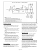
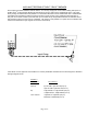
6. Using EMT conduit, flexible conduit, or 15 amp minimum rated MC cable, run a single circuit (Hot – Black, Neutral – White, and
Ground – Green) to feed power to the MVPN on terminals “L”, “N”, and “G” in the lower, right hand corner of enclosure on terminal
block TB-2. This circuit is considered “dirty power” since it has not been conditioned yet by the POWERVAR UPM and should not
be run in the same conduit as the “clean power” circuits that will feed power to all the “critical circuits”. Conductor size should be 14
AWG minimum.
7. Using EMT conduit, flexible conduit, or 15 amp minimum MC cable, run a single circuit (Hot – Black, Neutral – White, Safety
Ground – Green, and Isolated Ground – Green/yellow stripe) for each of the “critical circuits” from the MVPN to the panelboards.
Conductor size should be 14 AWG minimum. Continuous EMT conduit and / or MC cable (with the outer metal armor or sheath
containing a non-insulated ground wire rated for the return ground path) can perform the safety (equipment) ground function and
eliminate the need for the separate safety ground conductor. In these cases, the green insulated conductor becomes the Isolated
Ground conductor which terminates at the Isolated Ground receptacle ground lug. NOTE: For new installations, run the
“critical circuit” conduits / cables directly to the MVPN enclosure.
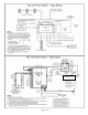
8. Terminate each set of conductors to the MVPN on terminals “LD 1 – LD 4”, “N”, “G”, and “IG” on terminal block TB1.
9. Before proceeding to step 10, be sure to communicate with local management that the “critical circuits” will have to be shut off
temporarily to perform the system tie in. Local management may want to power down certain computers and other equipment
before turning off the “critical circuit breakers”.
10. Turn off all the “critical circuit breakers” and verify that the equipment plugged into the “critical circuits” goes off.
11. Remove the hot conductor (black) from the breaker, neutral conductor (white) from the neutral bar, safety ground (green) from
the ground bar, and isolated ground (green/yellow stripe) from the isolated ground bar. Use wire nuts or butt connectors to sp
lice
each set of “critical circuit” conductors to each set of output conductors that terminate to the MVPN.
12. Remove all existing surge strips, filters, and / or UPS devices plugged into the “critical circuit” equipment receptacles.
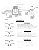
13. Turn the Transfer Switch on the MVPN to the RIGHT which is the “Bypass” position. Turn on the circuit breaker feeding input
power to the MVPN. Both the “Input” and “Output” pilot lights should be illuminated and all the connected “critical circuit” equipment
should come back on.
Page 2 of 8