Model 5010 POWER-TONGUE WINDROWER OPERATOR’S MANUAL 680 Moray Street Winnipeg, Manitoba R3J 3S3 (204) 885-5590, Fax 832-7749 9700 NW Conant Avenue Kansas City, Missouri 64153-1832 (816) 891-7313, Fax 891-7323
Inside Front Cover (blank)
INTRODUCTION Your new MacDon Model 5010 Power-Tongue Windrower is designed to cut, condition and lay in windrows, a wide variety of grasses and hay crops. Use this manual as your first source of information about the machine. If you follow the instructions given in this manual, your Windrower will work well for many years. The manual contains instructions for "Safety", "Operation", and "Maintenance/Service". In addition, "Unloading and Assembly" information is given towards the back of this book.
TABLE OF CONTENTS PAGE INTRODUCTION...................................................................................................................................1 SERIAL NUMBER LOCATION .............................................................................................................4 SAFETY Safety Alert Symbol..........................................................................................................................5 Signal Words................................................
TABLE OF CONTENTS PAGE MAINTENANCE/SERVICE Service Procedures.........................................................................................................................39 Recommended Fluids and Lubricants.............................................................................................40 Capacities of Enclosed Drives and Reservoir .................................................................................40 Bearing Installation.................................................
SERIAL NUMBER LOCATIONS Record the serial number in the space provided. Model 5010 Power Tongue Windrower: A Serial number plate (A) is located on the side of the left hand end frame. SERIAL PLATE LOCATION: WINDROWER Tongue: Serial number plate (B) is located at rear of tongue. B NOTE: When ordering parts and service, be sure to give your dealer the complete and proper serial number.
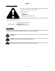
SAFETY SAFETY ALERT SYMBOL This safety alert symbol indicates important safety messages in this manual and on safety signs on the machine. This symbol means: ATTENTION! BECOME ALERT! YOUR SAFETY IS INVOLVED! Carefully read and follow the safety message accompanying this symbol. Why is SAFETY important to you? 3 BIG REASONS · ACCIDENTS DISABLE AND KILL · ACCIDENTS COST · ACCIDENTS CAN BE AVOIDED SIGNAL WORDS Note the use of the signal words DANGER, WARNING, and CAUTION with safety messages.
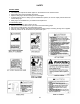
SAFETY SAFETY SIGNS • • • • The safety signs reproduced below appear on the windrower at the locations listed. Keep safety signs clean and legible at all times Replace safety signs that are missing or become illegible. If original parts on which a safety sign was installed are replaced, be sure the repair part also bears the current safety sign. • Safety signs are available from your Dealer Parts Department. To install safety signs: 1. Be sure the installation area is clean and dry. 2.
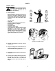
SAFETY GENERAL SAFETY The following are general farm safety precautions that should be part of your operating procedure for all types of machinery. 1. Protect yourself. When assembling, operating and servicing machinery, wear all the protective clothing and personal safety devices that COULD be necessary for the job at hand. Don't take chances. · · · · · · · You may need: a hard hat. protective shoes with slip resistant soles. protective glasses or goggles. heavy gloves. wet weather gear.
SAFETY GENERAL SAFETY (continued) 6. Wear close-fitting clothing and cover long hair. Never wear dangling items such as scarves or bracelets. 7. Keep hands, feet, clothing and hair away from moving parts. Never attempt to clear obstructions or objects from a machine while the engine is running. NEVER WEAR LOOSE OR DANGLING CLOTHES 8. Keep all shields in place. Never alter or remove safety equipment. Make sure driveline guards can rotate independently of the shaft and can telescope freely. 9.
SPECIFICATIONS DIMENSIONS Overall Width: Transport Position Field Position Overall Length: Transport Position Field Position Overall Height Transport Position Field Position Weight 12 FT. 14 FT. 16 FT. 13.5 ft. (4103 mm) 15.5 ft. (4713 mm) 18.1 ft. (5531 mm) 21.1 ft. (6446 mm) 17.5 ft. (5323 mm) 24.1 ft. (7360 mm) 20.7 ft. (6320 mm) 22.1 ft. (6740 mm) 15.8 ft. (4816 mm) 16.3 ft. (4975 mm) 24.9 ft. (7573 mm) 18.2 ft. (5557 mm) 6.2 ft. (1896 mm) 6.2 ft. (1896 mm) 5400 lbs. (2450 kg) 5800 lbs.
SPECIFICATIONS AUGER 12 FT. 14 FT. 16 FT. Drive Type Chain final drive Overload Protection Hydraulic motor Auger Type 20 in. (508 mm) diameter variable pitch, center feed Auger Speed 230 RPM CONDITIONER ROLLS Drive Type Drivelines from enclosed oil bath chain drive Roll Type Helical intermeshing steel bars Roll Diameter 10 in. (254 mm) Roll Length 93 in. (2360 mm) Roll Speed 750 RPM WHEELS Tread Width 119 in. (3030 mm) 143 in. (3640 mm) 167 in. (4250 mm) Tires 31 x 13.
TORQUE SPECIFICATIONS CHECKING BOLT TORQUE The tables shown below give correct torque values for various bolts and capscrews. Tighten all bolts to the torques specified in chart unless otherwise noted throughout this manual. Check tightness of bolts periodically, using bolt torque chart as a guide. Replace hardware with the same strength bolt. ENGLISH TORQUE SPECIFICATION NC Bolt Torque* Bolt Dia.
TORQUE SPECIFICATIONS TIGHTENING HYDRAULIC O-RING FITTINGS* 1. Inspect O-ring and seat for dirt or obvious defects. 2. On angle fittings, back the lock nut off until washer bottoms out at top of groove. Thread Size (in.) 3. Hand tighten fitting until back up washer or washer face (if straight fitting) bottoms on face and O-ring is seated. 4. Position angle fittings by unscrewing no more than one turn. 5. Tighten straight fittings to torque shown. 6.
OPERATION YOUR RESPONSIBILITIES AS AN OWNER/OPERATOR CAUTION: 1. It is your responsibility to read and understand this manual completely before operating the windrower. Contact your dealer if an instruction is not clear to you. 2. Follow all safety messages in the manual and on safety signs on the machine. 3. Remember that YOU are the key to safety. Good safety practices protect you and the people around you. 4.
OPERATION PREPARING THE TRACTOR 1. Select proper tractor size. The minimum power required is: 12 ft. - 60 hp (45 kw) 14 ft. - 75 hp (56 kw) 16 ft. - 90 hp (68 kw) Also, minimum hydraulics required are 1750 psi (12000 kPa) pressure with double acting, dual remote capability. 2. Adjust tractor drawbar to meet ASAE Standard specifications as listed below. An improperly located drawbar may affect header flotation and guard angle. (A) 14 in. (356 mm) for 540 rpm. 16 in. (406 mm) for 1000 rpm.
OPERATION PREPARING THE WINDROWER 1. Check the tires and inflate if necessary. Recommended pressure is 30 psi (207 kPa). CAUTION: When inflating tires, use a clip-on chuck and extension hose long enough to allow you to stand to one side and not facing the tire. 2. Check for proper assembly and adjustment and make sure all bolts are tightened securely. STAND TO ONE SIDE WHEN INFLATING TIRES 3. Check the tension of the reel drive belt and the sickle drive belt. Adjust if required.
OPERATION ATTACHING WINDROWER TO TRACTOR CAUTION: Shut off tractor, engage parking brake and remove key before working around hitch. A CAUTION: Never attach windrower to tractor rear axle or three-point hitch arms. 1. Using the jack, raise windrower tongue to clear the hitch pin in drawbar extension. Position tractor to align ball joint on tongue with hitch pin and lower tongue. Secure with lock pin (A). C 2.
OPERATION ATTACHING (cont'd) WINDROWER TO TRACTOR 5. Connect remote hydraulic hoses as follows: a. Connect the two tongue swing hoses (H) so that when the tractor control is moved forward, the swing cylinder will extend, moving the windrower to the right. When the tractor control handle is moved back, the swing cylinder will retract, moving the windrower to the left. H J K b.
OPERATION A BREAK-IN PERIOD 1. After attaching windrower to tractor for the first time, operate the machine slowly for 5 minutes, watching and listening FROM THE TRACTOR SEAT for binding or interfering parts. E CAUTION: Before investigating an unusual sound or attempting to correct a problem, shut off tractor, engage parking brake and remove key. H 2. Check wheel bolt torque after 1 hour operation and periodically thereafter (at least every 100 hours). Torque to 120 ft.lbs. (160 N⋅m).
OPERATION PRE-STARTING CHECKS Do the following at the start of each operating season: CAUTION: 1. Review the Operator's Manual to refresh your memory on safety and operating recommendations. 2. Review all safety signs and other decals on the windrower and note hazard areas. 3. Be sure all shields and guards are properly installed and secured. Never alter or remove safety equipment. 4. Be sure you understand and have practiced safe use of all controls.
OPERATION PRE-STARTING CHECKS Do the following each day before start-up: CAUTION: 1. Clear the area of other persons, pets etc. Keep children away from machinery. Walk around the windrower to be sure no one is under, on or close to it. 2. Remove foreign objects from the machine and surrounding area. 3. Wear close fitting clothing and protective shoes with slip resistant soles.
OPERATION OPERATE CORRECTLY CAUTION: 1. Follow all safety and operational instructions given in your tractor Operator's Manual. If you do not have a tractor manual, get one from your dealer and read it thoroughly. 2. Never attempt to start the tractor engine or operate the windrower except from the tractor seat. 3. Check the operation of all controls in a safe clear area before starting work. 4. Do not allow riders on tractor or windrower. 5.
OPERATION LIFT CYLINDER STOP (RAISING AND LOWERING WINDROWER) WARNING: To avoid bodily injury or death from fall of raised machine, always engage lift cylinder stops before going under windrower for any reason. To engage cylinder stops: 1. Raise machine to maximum height by activating remote cylinder control valve in tractor. NOTE: Hoses should be connected so that moving control lever (A) back raises the header. TRACTOR CONTROL LEVER (TYPICAL) 2.
OPERATION STEERING Steering the windrower is controlled by the tractor remote hydraulic system. This steering system allows the windrower to follow directly behind the tractor, make a full cut to either side, or any position in between. NOTE: To allow hitch to swing, latch rod must be in field position (D). If rod is in transport position (A), pivot rod retainer (C) up to allow moving rod from (A) to (D).
OPERATION 180° TURN When cutting back and forth on one side of the field, approximately 50 ft. (15 m) is required at each end of the field to make a 180° turn-around. Proceed as follows: 1. Beginning at position (A), the tractor is guided away from the uncut crop while the windrower is guided straight ahead until cutting through the end. 2.
OPERATION TURNING SQUARE CORNERS The following procedure is intended only as a guide to developing a turning procedure for the tractor being used. Specific distances are not given due to the variances in tractor maneuverability. 1. As the tractor approaches the corner, guide the tractor sharply away from the crop. Steer the windrower to maintain a straight cut ahead as the tractor moves away from the crop. 2.
OPERATION LEAN BAR POSITION IMPORTANT: To prevent structural damage to the header, do not operate with lean bar removed. Use the lean bar adjustment to accommodate different crop heights. The lean bar should strike the upper portion of the crop, leaning it away from the header and exposing the stalks to the sickle. A To extend or retract lean bar, re-position hardware (A) in adjustment holes as required.
OPERATION REEL SPEED For best feeding of the crop into the auger, reel speed should be just faster than ground speed. This gently sweeps material across the sickle into the auger. The reel speed is factory set at 66 rpm. With a pulley position exchange, other reel speeds are possible. (See chart.) A slower reel speed will reduce excessive crop carry-over, while a faster reel speed will result in a more even stubble height in down and tangled crops.
OPERATION REEL POSITION (continued) NOTE: The reel must be adjusted equally on both sides, both horizontally and vertically. To adjust reel horizontal (fore-aft) position: a. Loosen nuts (A) and (B). Back off nut (C) until reel drive chain and belt are loose. b. Loosen nuts (D), three on left side, four on right side. c. Loosen jam nut on bolt (E), both sides, and turn adjuster nuts to move reel fore or aft to desired position. Tighten jam nut. d.
OPERATION CUTTING HEIGHT Control cutting height with skid plates, not with the hydraulic cylinder. Having the header "ride" on the skid plates allows the float linkage to float header over obstacles and follow ground contours, rather than supporting the header with the cylinder. NOTE: Lowering the skid plates raises the cutting height. This may be desirable in stony conditions, to reduce damage to cutting components. Also, a longer stubble length helps material dry faster.
OPERATION CUTTERBAR ANGLE Cutterbar angle can be varied from 6° to 11.5° below horizontal. Choose an angle that maximises performance for your crop and field conditions. A flatter guard angle provides better clearance in stony conditions while a steeper guard angle is required in down crops for better lifting action. To adjust cutterbar angle: a. Loosen nut (A). b. To decrease (flatten) cutterbar angle, turn nut (B) clockwise. c. To increase (steepen) cutterbar angle, turn nut (B) counter-clockwise. d.
OPERATION HEADER FLOTATION Header flotation springs are normally set so 70 lbs. force (311 N) is required to lift either end of the header just off the ground. In rough or stony conditions, it may be desirable to change setting to 35-50 lbs. (156-222 N) to protect cutting components. NOTE: When float setting is light, it may be necessary to use a slower ground speed to avoid excessive bouncing and leaving a ragged cut. To increase header flotation, which decreases the force required to lift header: a.
OPERATION ROLL GAP WARNING: To avoid bodily injury or death from unexpected start-up or fall of raised machine; stop engine, remove key and engage lift cylinder stop before going under machine to examine rolls or for any other reason. Steel rolls "condition" the crop by crimping the stem in several places. This allows moisture release for quicker drying. The degree to which the crop is conditioned as it passes through the rolls is controlled by roll gap (A), measured from bar to roll tube.
OPERATION FORMING SHIELDS WARNING: Keep hands and feet away from discharge opening. Keep everyone several hundred feet away from your operation. Never direct the discharge toward anyone. Stones or other foreign objects can be ejected with force. The position of the forming shields controls the width and placement of the windrow.
OPERATION HAYING TIPS There is one certainty when making hay - a quick cure will maintain top quality. It is critical to have the cured hay baled as quickly as possible, for two reasons: 1. Every day hay lies on the ground, 5% of the protein is lost. 2. The sooner the cut hay is off, the earlier the start for next growth. Generally, leaving the windrow as wide and thin as possible makes for the quickest curing, however there are other factors which affect curing time: 1.
OPERATION HAYING TIPS (continued) 3. WINDROW CHARACTERISTICS See "Operating Variables" in this section. Control the factors listed to produce a windrow with the following characteristics: a. High and fluffy for good air flow. The movement of air through the windrow is more important to the curing process than direct sunlight. b. Consistent formation, not bunchy. A uniform windrow permits an even flow of material into the baler, chopper etc. c.
OPERATION UNPLUGGING THE WINDROWER WARNING: Stop tractor engine and remove key before removing plugged material from windrower. A child or even a pet could engage the drive. If the sickle plugs: 1. Stop forward movement of the tractor and stop the PTO. 2. Lift the cutterbar about 12 inches (300 mm). 3. Back up about 3 feet (1 metre) while slowly engaging the PTO. 4. If the plug does not clear; raise machine, shut off engine, remove key and lock tractor brakes. 5. Engage lift cylinder stop.
OPERATION SHUT-DOWN PROCEDURE CAUTION: Before leaving the tractor seat for any reason: 1. 2. 3. 4. 5. 6. Stop engine and remove key from ignition. 7. Wait for all movement to stop. 8. Lock tractor anti-vandalism covers and closures when leaving the machine unattended. Park on level ground if possible. Lower the windrower fully. Place all controls in NEUTRAL or PARK. Disengage PTO. Engage the park brake.
OPERATION TRANSPORTING THE WINDROWER: FLATBED B CAUTION: Use the following procedure when shipping the windrower on a flatbed trailer. 1. Raise header with tractor hydraulics and install lift cylinder stops. 2. Position lean bar to hang vertically downward. Install only one bolt per side. (Remove divider rods, if equipped.) 3. Remove complete rear forming shield group, in whole. 4. At tongue pivot, back off two 5/8 nuts (B) approximately 3/4 inch (20 mm).
OPERATION MAINTENANCE/SERVICE STORAGE PROCEDURE SERVICE PROCEDURES Do the following at the end of each operating season: CAUTION: To avoid personal injury, before servicing windrower or opening drive covers: CAUTION: 1. Fully lower the windrower. If necessary to service in the raised position, always engage lift cylinder stops. 1. Clean the windrower thoroughly. Never use gasoline, naphtha or any volatile material for cleaning purposes. These materials may be toxic and/or flammable. 2.
MAINTENANCE/SERVICE RECOMMENDED FLUIDS AND LUBRICANTS GREASE Use an SAE Multi-Purpose High Temperature Grease with Extreme Pressure (EP) Performance and containing at least 1.5% molybdenum disulphide. (NLGI Grade 2) Also acceptable is an SAE Multi-Purpose Lithium Base Grease. HYDRAULIC OIL Use single grade trans-hydraulic oil. To prevent machine damage, do not use engine oil.
MAINTENANCE/SERVICE DRIVE SHIELDS The left and right side drive shields, in the open position, rest in a hinge "pocket" to prevent them from falling. To close drive shields, lift up on shield to clear hinge pocket at (F), then lower shield and secure with rubber latch. F CLOSING DRIVE SHIELDS GREASING THE WINDROWER See "Recommended Lubricants" in this section for recommended greases.
MAINTENANCE/SERVICE GREASING THE WINDROWER (continued) 50 Hours: 1. Main Drive Shaft Bearings (A) & (B) - two fittings 4. Roll Shaft Bearings (G) & (H) - four fittings B H G A LEFT SIDE RIGHT SIDE ROLL SHAFT BEARINGS MAIN DRIVE SHAFT BEARINGS 2. Reel Shaft Bearings (C) & (D) - two fittings C D E REEL SHAFT BEARING - LEFT SIDE 3.
MAINTENANCE/SERVICE GREASING THE WINDROWER 50 Hours: (continued) 5. Frame-to-Header Pivot (J) - two fittings 7. Tongue Pivot (L) - one fitting J L TONGUE PIVOT 8. Transport Lock Pin (M) - one fitting FRAME-TO-HEADER PIVOT 6. Lower Float Link Bushings (K) - two fittings M TRANSPORT LOCK PIN K 9.
MAINTENANCE/SERVICE GREASING THE WINDROWER (continued) 100 Hours: 1. Wheel Hub Bearings (D) - two fittings D WHEEL HUB BEARINGS CENTER LINK BALL JOINTS HITCH PIN LOCK NUT Apply SAE 30 or equivalent lightweight oil to the center link ball joints (A) every 50 hours. Check hitch pin nut (C) every 50 hours. Maintain 350 ft. lbs. (475 N⋅m) torque. A C CHECK HITCH PIN LOCK NUT OIL CENTER LINK BALL JOINTS SPRING PIVOTS Apply SAE 30 or equivalent lightweight oil to the spring pivots (B) every 50 hours.
MAINTENANCE/SERVICE HYDRAULICS The windrower is hydraulically powered using: 1. A self-contained hydraulic system to operate the header functions. 2. The tractor remote system to operate the header lift cylinder and steering cylinder. Hydraulic Hoses and Lines Check hydraulic hoses and lines daily for signs of leaks. WARNING: Avoid high-pressure fluids. Escaping fluid can penetrate the skin causing serious injury. Relieve pressure before disconnecting hydraulic lines.
MAINTENANCE/SERVICE HYDRAULICS: Hydraulic Reservoir (continued) Change hydraulic oil every 600 hours or 3 years. To drain the reservoir: 1. Loosen hydraulic fitting and remove filler plug as described under "To add hydraulic oil", previous page. 2. Disconnect the pump supply hose (A) from the pump. NOTE: A drain pan with a capacity of 130 litres (35 U.S. gallons) will be required. A Hydraulic Oil Filter Change hydraulic oil filter (B) after the first 100 hours operation and every 250 hours thereafter.
MAINTENANCE/SERVICE SICKLE AND SICKLE DRIVE WARNING: Keep hands clear of the area between guards and sickle at all times. CAUTION: Wear heavy gloves when working around or handling sickles. KEEP HANDS AWAY FROM SICKLE Sickle Lubrication Apply SAE 10 or equivalent light weight oil daily (one or two drops per section) along entire length of sickle. NOTE: Do not oil sickle if operating in sandy conditions. Oil will cause sand to adhere to sickle components, resulting in excessive wear.
MAINTENANCE/SERVICE SICKLE AND SICKLE DRIVE (continued) Sickle Head Needle Bearing Installation Using a flat-ended tool (A) with approximately the same diameter as the bearing, push the bearing into the sickle head until the top of the bearing is flush with the step (B) in sickle head. IMPORTANT: Assemble the bearing with the stamped end (the end with identification markings) against the tool. Install seal (C) in top of sickle head with lip facing outwards.
MAINTENANCE/SERVICE SICKLE AND SICKLE DRIVE (continued) Guards Check daily that guards are aligned to obtain proper shear cut between sickle section and guard. Sickle sections should contact shear surface of each guard. A Align guards with guard straightening tool provided as shown: To bend guard tips up, position tool as shown at (A) and pull up. BENDING GUARD TIPS UP To bend tips down, position tool as at (B) and push down. NOTE: Tool is stored in toolbox at right end of main frame.
MAINTENANCE/SERVICE SICKLE AND SICKLE DRIVE (continued) Sickle Drive Belt Tension IMPORTANT: To prolong belt and drive life, do not over-tighten belt. A To adjust: 1. Loosen nut (A) securing idler pulley. 2. Using a punch or screwdriver in pry holes (B), raise idler until a force of 12 lbs. (55 N) deflects belt 1/2 inch (13 mm) at mid-span. B 3. Tighten nut (A). 4. Re-adjust tension of a new belt after a short run-in period, (about 5 hours). SICKLE DRIVE BELT TENSION ADJUST.
MAINTENANCE/SERVICE SICKLE AND SICKLE DRIVE (continued) Wobble Box Maintenance Mounting Bolts - Check four wobble box mounting bolts (B) torque after the first 10 hours operation and every 100 hours thereafter. Torque should be 200 ft.lbs. (270 N⋅m). When tightening, start with the side mounting bolts. A Lubricant - Check wobble box lubricant level before first operation and every 100 hours thereafter. To check: D 1. Raise header to a point where the wobble box base is approximately level. 2.
MAINTENANCE/SERVICE REEL AND REEL DRIVE Reel Drive Chain Lubrication Lubricate chain daily with a light weight oil (SAE 30). Apply oil to upper edge of lower chain span (A). A OIL REEL DRIVE CHAIN Reel Drive Chain Tension To tighten reel drive chain: A 1. Loosen nuts (A) and (D) securing reel drive arm to frame. D 2. Push pulley (B) up and back until total chain slack at (C) is 1/2 in. (13 mm). Be sure chain tension is sufficient to remove excess belt play. B C 3. Tighten nut (A). 4.
MAINTENANCE/SERVICE AUGER AND AUGER DRIVE Auger Position The auger position has been factory set and should not normally require adjustment. For nearly all conditions, the auger performs best when set as close as possible to the stripper bars without rubbing. This is especially important in grass and other crops which have a tendency to wrap. Component wear may cause clearances to become excessive, resulting in feeding problems and uneven windrows. A Should adjustment be required: 1.
MAINTENANCE/SERVICE AUGER AND AUGER DRIVE Stripper Bars To adjust: 1. Position auger for clearance to strippers (A) and (B), as shown. 2. Loosen bolts (H) along upper stripper bar. 3. Slide extension bars (J) in or out to obtain approximately 1/8 inch (3 mm) clearance to auger flighting (K) along entire auger length. 4. Tighten bolts (H).
MAINTENANCE/SERVICE AUGER AND AUGER DRIVE (continued) Auger Drive Chain Lubrication A Lubricate chain (A) daily with lightweight oil (SAE 30). OIL AUGER DRIVE CHAIN Auger Drive Chain Tension To tighten auger drive chain: 1. Loosen idler sprocket mounting bolt (K). 2. Using a punch or screwdriver in pry holes (L), move sprocket upward until deflection at (M) is 1/4 inch (6 mm). 3. Tighten bolt (K). Auger Drive Belt Tension IMPORTANT: To prolong drive life, do not overtighten belt.
MAINTENANCE/SERVICE ROLLS AND ROLL DRIVE Roll Drive Chain Tension Check chain tension after the first 10 hours operation and every 100 hours or annually thereafter, as follows: 1. Remove rubber plug at left side of chain case. (See "Roll Drive Chain Case Lubricant" below.) 2. Chain should deflect a maximum 1/4 inch (6 mm) each way. C B 3. If adjustment is required: a. b. c. d. Loosen nut (B). Loosen two bolts (C). To tighten chain, rotate cam clockwise, using a 15/16 wrench on welded nut (D).
MAINTENANCE/SERVICE ROLLS AND ROLL DRIVE (continued) Roll Timing For proper conditioning, the rolls must be timed with each steel bar on one roll centered between two bars of the other roll as shown. WARNING: To avoid bodily injury or death from unexpected start-up or fall of raised machine; stop engine, remove key and engage lift cylinder stops before going under machine to examine roll timing, or for any reason.
MAINTENANCE/SERVICE ROLLS AND ROLL DRIVE (continued) Roll Drive Chain Removal B 1. Raise header. Stop engine, remove key and engage lift cylinder stops. 2. Remove bolts securing upper cover (A) to chain case. Loosen clamp bolt (B) and slide the cover down the drive shaft shield. A 3. Remove bolts securing lower cover (C) and remove cover. C REMOVE COVERS 4. Loosen two bolts (D) and nut (L) at chain tensioner. E D 5. Rotate tensioner cam counter-clockwise, using a 15/16 wrench on welded nut (E).
MAINTENANCE/SERVICE ROLLS AND ROLL DRIVE (continued) Roll Drive Chain Installation IMPORTANT: To ensure proper chain quality, service with Genuine MacDon Part only. 1. Feed the chain into chain case. 2. Lift chain up to driver sprocket (H) and engage on first few teeth. 3. Turn sickle drive pulley at left end of header to rotate driver sprocket counter-clockwise until chain engages upper roll sprocket (J) as shown. ENGAGE DRIVER AND UPPER SPROCKETS 4.
MAINTENANCE/SERVICE WHEELS AND TIRES 1 Wheel Bolts Check and tighten wheel bolts after the first 1 hour operation and every 100 hours thereafter. 6 3 Whenever a wheel is removed and re-installed, check torque after one hour of operation. Maintain 120 ft. lbs. (160 N.m) torque. 4 Follow proper bolt tightening sequence shown. Be sure valve stem (A) points away from wheel support. A 5 CAUTION: When installing wheel be sure to use the holes that are countersunk to match bolt head profile.
MAINTENANCE/SERVICE MAINTENANCE SCHEDULE The following maintenance schedule is a listing of periodic maintenance procedures, organized by service intervals. For detailed instructions, see the specific headings in Maintenance/Service section. Use "Recommended Fluids and Lubricants" as specified under that heading. Service Intervals The recommended service intervals are in hours of operation. IMPORTANT: Recommended intervals are for average conditions.
MAINTENANCE RECORD ACTION: 4 - Check λ - Lubricate σ - Change Hour Meter Reading: Serviced By: Maintenance Procedure BREAK-IN λ 10 HOURS OR DAILY Roll Universal Shafts 4 Hydraulic Oil Level 4 Hydraulic Hoses & Lines λ Sickle Assembly 4 Sections, Guards, Hold-downs λ Reel Drive Chain λ Auger Drive Chain 4 Tire Pressure λ 25 HOURS Sickle Head λ 50 HOURS Tongue Pivot, Transport Lock λ Main Drive Shaft Bearings λ Reel Shaft Bearings λ Auger Shaft Bearings λ Roll Shaft Bearings λ
TROUBLE SHOOTING SYMPTOM PROBLEM SOLUTION REF. Excessive breakage of sickle sections or guards. Cutting height too low in stony conditions. Raise cutting height with skid plates. 29 Cutterbar angle too steep in stony conditions. Decrease cutterbar angle 30 Header flotation too heavy in stony conditions Adjust to lighter float setting. 31 Guards, sickle and holddowns misaligned. Straighten guards, align hold-downs. 49 Ground speed too high in stony conditions. Reduce ground speed.
TROUBLE SHOOTING SYMPTOM PROBLEM SOLUTION REF. Ragged or uneven cutting of crop. (continued) Bent or misaligned guards causing poor shearing action. Align guards for proper shearing action. 49 Header flotation too light, causing bouncing. Adjust to heavier float setting. 31 Ground speed too fast. Slow down. Ground speed should not exceed 8 mph (13 km/h). 26 Sickle drive belt too loose. Increase belt tension. 50 Reel drive chain too loose. Increase chain tension.
TROUBLE SHOOTING SYMPTOM PROBLEM SOLUTION REF. Leaving small strip of flattened, uncut material. Ground speed too fast. Slow down. 26 Crowding of the uncut material. Steer tractor slightly away from uncut crop. --- Reel position incorrect. Move reel forward and down. 28 Sickle sections or guards are worn or broken. Replace worn or broken parts. 47 Extremely thick or wet undergrowth. Raise cutting height to clear undergrowth. 29 Move reel back and down (close to guards).
TROUBLE SHOOTING SYMPTOM PROBLEM SOLUTION REF. Excessive heating of hydraulic oil. Relief pressure too low. Replace relief valve. 46 Rolls plugging. Roll gap too large for proper feeding. Decrease roll gap. 32 Roll gap too small in thick stemmed canetype crops. Increase roll gap. 32 Ground speed too fast. Slow down. 26 Rolls improperly timed. Adjust roll timing. 57 Feeding aids for shorter, lighter crop impede flow of heavy or thick stemmed crops (cane, sudan grass etc.).
OPTIONS & ATTACHMENTS The following attachments and optional equipment are available from your Dealer: ADDITIONAL SKID PLATES WholeGoods order number: B2149 In addition to the standard two outer skid plates, two inner plates may be added for extra control of cutting height and protection of cutting components. See "Cutting Height" in Operation section.
UNLOADING & ASSEMBLY PREPARE TO UNLOAD CAUTION: To avoid injury to bystanders from being struck by machinery, do not allow persons to stand in unloading area. 1. Move trailer into position and block trailer wheels. 2. Lower trailer storage stands. CAUTION: Unloading equipment must meet or exceed the specified requirements. Using inadequate equipment may result in chain breakage, vehicle tipping or machine damage. PREPARE TO UNLOAD LIFTING VEHICLE REQUIREMENTS Use a lifting vehicle with a minimum 8000 lb.
UNLOADING & ASSEMBLY UNLOAD TONGUE Attach chain to two brackets (A) on top of tongue. A ATTACH CHAIN TO TONGUE BRACKETS LOWER WINDROWER TO WORKING POSITION E 1. Choose an area with level ground. Rest each tire on two 2x4's (side by side) or one 2x6 (B) to provide ground clearance and prevent damage to conditioner shield when windrower is lowered. 2. Block wheels at (C) and set 14 inch (350 mm) blocks (D) for support at rear of skid plates. 3. Remove deflectors (E).
UNLOADING & ASSEMBLY INSTALL TONGUE IMPORTANT: If there is more than one machine to be assembled, and they are different sizes (12 ft., 14 ft., 16 ft.), be sure the proper tongue is matched to each unit. Tongues are identified on a plastic tag tied to the hose support near the front end. Should this tag be missing, tongues can be identified by length as follows: HEADER SIZE 12 ft. 14 ft. 16 ft.
UNLOADING & ASSEMBLY ATTACH HYDRAULICS AND ELECTRICAL 1. Attach barrel end (A) of shift cylinder to bracket on hitch. Attach rod end (B) to bracket on frame tube. Secure pins with cotter pins. A B NOTE: It may be necessary to loosen a fitting to allow extension of cylinder rod. INSTALL SHIFT CYLINDER 2. Attach lift cylinder hoses to hydraulic lines at (N) and (P) on top of tongue. R N NOTE: Connect hose from left lift cylinder to left hydraulic line, right cylinder hose to right hydraulic line. 3.
UNLOADING & ASSEMBLY ATTACH HYDRAULICS AND ELECTRICAL (continued) L 4. Attach motor to header primary drive: B R NOTE: For easier installation of motor onto shaft, hoses may be completely removed from motor at swivel fittings. A minimal amount of oil will drip out, however extreme care must be taken to prevent dirt from entering at hose ends and motor ports. If removing hoses, go to step (c).
UNLOADING & ASSEMBLY ATTACH HYDRAULICS AND ELECTRICAL (continued) 4. Attach motor to header primary drive, cont’d: * See previous page for illustrations and photos. d) Attach torque arm (H) to motor: - Orient torque arm with 21/32" (17 mm) dimension as shown. - Position free end of arm to achieve dimension (S) = 8.75" (222 mm) and torque hex nut (J) to 50 ft.lbs. (68 N⋅m), then securely tighten lock nut (K) against hex nut. e) Reattach torque arm (H) to frame, tightening hardware as in step 4d.
UNLOADING & ASSEMBLY ATTACH HYDRAULICS AND ELECTRICAL (continued) HOSE & HARNESS ROUTING 6. Tie wiring harness to motor hoses with 3 large plastic ties evenly spaced. Secure any excess harness with small plastic ties at (R) (see top photo, page 72). 7. Remove top clamp (Y) and place 2-lift cylinder hoses (U). Replace top clamp. 8. Mount pump (S) in storage position at front of tongue.
UNLOADING & ASSEMBLY INSTALL HOOD AND DEFLECTORS 1. Loosen hardware J/K and F/G. B C D E F G H WASHER - lock, 1/2 BOLT - hex head, 1/2 NC x 1 inch NUT - lock, smooth flange 3/8 NC BOLT - round hd, square neck 3/8 NC x 3/4" NUT - serrated flange, 1/2 NC BOLT - round hd, square neck 1/2 NC x 1" NUT - hex, 3/4 NC (Tighten lower nut to 100 ft.lbs. Then, holding lower nut with a wrench, tighten top nut against lower nut.) J WASHER - flat, 21/32 inch I.D. K NUT - hex, 5/8 NC 2. Swing hood into position. 3.
UNLOADING & ASSEMBLY ADJUSTMENTS AND CHECKS Perform the final checks and adjustments as listed on the "Pre-Delivery Checklist" (yellow sheet) to ensure the machine is field-ready. IMPORTANT: To avoid machine damage, check that no shipping dunnage has fallen down between auger and pans.
INDEX L A PAGE Assembly....................................................... 68 Attaching the Windrower ............................... 16 Attachments .................................................. 67 Auger Drive Chain Lubrication ...................... 55 Auger Drive Chain Tension ........................... 55 Auger Position ............................................... 53 Auger Paddle Kit ........................................... 67 PAGE Lean Bar Position.....................................
INDEX S PAGE Safety (continued) - Signs .......................................................... 6 - Storage Procedure ................................... 39 - Transporting ............................................. 37 - Your Responsibilities................................ 13 Serial Number Locations ................................. 4 Service Procedures ....................................... 39 Shields, closing ............................................. 41 Shut-Down Procedure ....................
Power-Tongue Windrower Pre-Delivery Checklist Perform these checks and adjustments prior to delivery to your customer. See the Operator's Manual for adjustment details. CAUTION: Carefully follow the instructions given. Be alert for safety related messages which bring your attention to hazards and unsafe practices. Windrower Serial Number: Tongue Serial Number: Check for shipping damage or missing parts. Be sure all shipping dunnage is removed. Check sickle drive belt tension. (P.
The Quiet Leader 46627 Issue 01/01 Sugg. Retail: $15.