Model 963 30’ & 36’ HARVEST HEADERS OPERATOR’S MANUAL Form 147277 Issue 10/04 Sugg. Retail: $15.
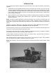
INTRODUCTION Your new 963 Harvest Header is designed to serve a dual function in your grain and specialty crop harvesting operation: 1. Teamed with your self-propelled windrower power unit, the header will cut and lay crop into uniform fluffy windrows. Windrowing allows starting the harvest earlier, protects the crop from wind damage, and gives you more flexibility in scheduling combine time.
TABLE OF CONTENTS INTRODUCTION.........................................................................................................................................1 SERIAL NUMBER LOCATION....................................................................................................................4 SAFETY Safety Alert Symbol................................................................................................................................4 Signal Words...................................
TABLE OF CONTENTS MAINTENANCE/SERVICE Service Procedures..............................................................................................................................36 Closing L/H Drive Shield ......................................................................................................................36 Recommended Lubricants ...................................................................................................................37 Enclosed Drive Lubricant Capacities ....
SERIAL NUMBER LOCATION Record the serial number in the space provided. Harvest Header: Plate is located on gusset at left hand end sheet, near main tube. HEADER SERIAL PLATE NOTE: When ordering parts and service, be sure to give your dealer the complete and proper serial number. SAFETY SAFETY ALERT SYMBOL This safety alert symbol indicates important safety messages in this manual and on safety signs on the header.
SAFETY SIGNAL WORDS Note the use of the signal words DANGER, WARNING, and CAUTION with safety messages. The appropriate signal word for each message has been selected using the following guidelines: DANGER – Indicates an imminently hazardous situation that, if not avoided, will result in death or serious injury. WARNING – Indicates a potentially hazardous situation that, if not avoided, could result in death or serious injury. It is also used to alert against unsafe practices.
SAFETY SAFETY SIGNS HEADER FRAME BACK TUBE BACK TUBE BACK TUBE R/H WHEEL BEAM (TRANSPORT OPTION) HITCH (TRANSPORT OPTION) 6
SAFETY GENERAL SAFETY The following are general farm safety precautions that should be part of your operating procedure for all types of machinery. 1. Protect yourself. When assembling, operating and servicing machinery, wear all the protective clothing and personal safety devices that COULD be necessary for the job at hand. Don't take chances. · · · · · · · You may need: a hard hat. protective shoes with slip resistant soles. protective glasses or goggles. heavy gloves. wet weather gear.
SAFETY GENERAL SAFETY (continued) 6. Wear close-fitting clothing and cover long hair. Never wear dangling items such as scarves or bracelets. 7. Keep hands, feet, clothing and hair away from moving parts. Never attempt to clear obstructions or objects from a machine while the engine is running. 8. Keep all shields in place. Never alter or remove safety equipment. Make sure driveline guards can rotate independent of the shaft and can telescope freely. NEVER WEAR LOOSE OR DANGLING CLOTHES 9.
SPECIFICATIONS 963 HARVEST HEADER SICKLE DRIVE SICKLE SPEED SICKLE TYPE WINDROWER (Specs listed may vary depending on combine) "C" belt to single wobble box (enclosed oil bath) 1300 strokes/minute 1240-1345 strokes/minute Over-serrated, bolted sections DELIVERY OPENING WIDTH (between rollers) DELIVERY OPENING HEIGHT at 8" (200 mm) cutting height CUTTERBAR RANGE ground to guard tip, (varies with guard angle and options) 35" (890 mm) to 66" (1676 mm) 34" to 37" (880 to 950 mm) 2.
TORQUE SPECIFICATIONS CHECKING BOLT TORQUE The tables shown below give correct torque values for various bolts and capscrews. Tighten all bolts to the torques specified in chart unless otherwise noted throughout this manual. Check tightness of bolts periodically, using bolt torque chart as a guide. Replace hardware with the same strength bolt. ENGLISH TORQUE SPECIFICATION NC Bolt Torque* Bolt Dia.
TORQUE SPECIFICATIONS TIGHTENING O-RING FITTINGS* 1. Inspect O-ring and seat for dirt or obvious defects. 2. On angle fittings, back the lock nut off until washer bottoms out at top of groove. Thread Size (in.) 3. Hand tighten fitting until back-up washer or washer face (if straight fitting) bottoms on face and O-ring is seated. Nut Size Across Flats (in.
OPERATION YOUR RESPONSIBILITIES AS AN OWNER/OPERATOR CAUTION: 1. It is your responsibility to read and understand this manual and the Windrower or Combine Operator's Manual completely before operating the header. Contact your dealer if an instruction is not clear to you. 2. Follow all safety messages in the manuals and on safety signs on the machine. 3. Remember that YOU are the key to safety. Good safety practices protect you and the people around you. 4.
HEADER OPERATION BREAK-IN PERIOD 1. After attaching header to combine or windrower tractor for the first time, operate the machine with reel, drapers and sickle running slowly for 5 minutes, watching and listening FROM THE OPERATOR'S SEAT for binding or interfering parts. CAUTION: Before investigating an unusual sound or attempting to correct a problem, shut off engine, engage parking brake and remove key. NOTE: Reel and side drapers will not operate until oil flow fills the lines. A 2.
HEADER OPERATION PRE-STARTING CHECKS: ANNUAL PRE-STARTING CHECKS: DAILY Do the following at the start of each operating season. Do the following each day before start-up: CAUTION: CAUTION: 1. Review the Operator's Manuals to refresh your memory on safety and operating recommendations. 1. Clear the area of other persons, pets etc. Keep children away from machinery. Walk around the header to be sure no one is under, on or close to it. 2.
HEADER OPERATION OPERATE CORRECTLY CAUTION: 1. Follow all safety and operational instructions given in your Operator's Manuals. If you do not have a windrower tractor and/or combine manual, get one from your dealer and read it thoroughly. 2. Never attempt to start the engine or operate the machine except from the operator's seat. 3. Check the operation of all controls in a safe clear area before starting work. 4. Do not allow riders on windrower or combine. DO NOT ALLOW RIDERS 5.
HEADER OPERATION HEADER CONTROLS CAUTION: Be sure all bystanders are clear of machine before starting engine or engaging any header drives. See your Windrower Tractor or Combine Operator's Manual for identification of in-cab controls for: • Header Drive Clutch • Header Height • Ground Speed • Reel Speed • Reel Height HEADER LIFT CYLINDER STOPS DANGER: To avoid bodily injury or death from fall of raised header, always engage cylinder stops before going under header for any reason.
HEADER OPERATION Operating Variables OPERATING VARIABLES Satisfactory function of the header requires making the proper adjustments to suit various crops and conditions. 1. 2. 3. 4. 5. 6. 7. 8. 9. 10. Correct operation reduces crop loss and allows cutting of more acres. As well, proper adjustments and timely maintenance will increase the length of service you receive from the machine. The variables listed at right will affect the performance of the header.
HEADER OPERATION Operating Variables (continued) CUTTING HEIGHT Cutting height will vary, depending on whether windrowing or straight-cutting, type of crop, etc. See "Windrowing" for stubble height recommendations. Gauge Wheel Field Positions: For headers equipped with gauge wheels or the gauge wheel/transport package, choose Field Position 1 or 2 to maintain proper gauge wheel spring force at desired cutting height.
HEADER OPERATION Operating Variables CUTTING HEIGHT (continued) Skid Shoes (Attachment) Skid shoes are available as an attachment. The primary benefits of skid shoes are: 1. Help prevent damage to cutting components. 2. Reduce scooping of dirt onto cutterbar. 3. Provide a method of setting a minimum cutting height. To adjust skid shoes: 1. Raise header and engage lift cylinder stops. DANGER: To avoid bodily injury or death from fall of raised header, always engage cylinder stops before going under header.
HEADER OPERATION Operating Variables (continued) HEADER FLOTATION IMPORTANT: To avoid frequent breakage of sickle components, scooping soil, or soil build-up at cutterbar in wet conditions, set header float as light as possible without causing excessive bouncing. Under normal conditions, adjust float spring tension so 50 to 70 lbs. force (220 to 310 N) is required to lift cutterbar off ground at each end. See "Header Flotation" in Windrower or Combine Adapter Operator's Manual for adjustment details.
HEADER OPERATION Operating Variables To adjust delivery opening width (continued) 2. Remove screws from draper connector slat. 3. Use the following chart to position draper connector tubes at the appropriate rows of holes and position rollers at center opening for the desired application. CENTER DELIVERY OPENING WIDTH (W) (between rollers) LEG TO ROLLER EDGE (DIM. X) Row A to Row F (both drapers) 33.9" (860 mm) 22.
HEADER OPERATION Operating Variables To adjust delivery opening width 3. continued) Bolt opening adjustment bars to deck at the hole corresponding to the draper row. For example if drapers are to be connected at row E (from chart on previous page), move roller until hole (E) aligns with deck mounting slot. Use a carpenter’s square to ensure roller is square to deck and tighten hardware.
HEADER OPERATION Operating Variables END DELIVERY: The left deck of the 963 header can be manually shifted to close off the center opening and deliver crop to the left end of the header. This provides the capability of windrowing with a combine or non-windrower tractor as the power unit. To shift left deck: 1. Reverse draper travel by disconnecting hydraulic hoses at (B) and connect to opposite lines. 2. Remove deck retainer clips at cutterbar, item (G) on previous page.
HEADER OPERATION Operating Variables (continued) REEL SPEED • Reel speed affects the smoothness and evenness of the delivered crop. Operating the reel too fast or too slow relative to ground speed will cause bunching. • In standing crop, reel speed should be just faster than ground speed, sweeping crop across the sickle. • A faster reel speed may be necessary in leaning or down crop.
HEADER OPERATION Operating Variables DIVIDER ANGLE The dividers can be angled in or out to provide proper separation and clean entry in a variety of crops. Divider gather is factory set at approximately 1.5 inches (40 mm). In tangled crops like canola, it may be necessary to reduce gather. A To adjust angle, loosen hardware (A), position divider and tighten hardware. NOTE: On left side, ensure that front hinge pin of side shield remains covered.
HEADER OPERATION Windrowing The factors listed below will all affect the formation of the windrow. You will quickly become adept at adjusting these variables to achieve the desired results. NOTE: Crop condition is a major factor in forming a good windrow. While standing or uniformly leaning crops can generally be easily formed into an acceptable windrow, such is not the case when stalks are tangled or leaning in several directions.
HEADER OPERATION Windrowing DELIVERY OPENING The width and position of the delivery opening affects the width and configuration of the windrow.
HEADER OPERATION Windrowing WINDROW CHARACTERISTICS There are three basic criteria by which the quality of a windrow is measured: 1. Weight Distribution - heads and stalks distributed evenly across full width of windrow. 2. Good Curing - a loose, open windrow for better drying. 3. Good Weatherability - a well formed windrow that supports heads off the ground and holds together in extreme weather conditions. HERRINGBONE WINDROW The most desirable form of windrow, stalks are crossed and interwoven.
HEADER OPERATION Windrowing WINDROW CHARACTERISTICS (continued) PARALLEL WINDROW The stalks are parallel to windrow and heads evenly distributed across width of windrow. This windrow can be formed by center delivery or end delivery. Windrow rating: Weight Distribution: Good Curing Characteristics: Good Weatherability: Good PARALLEL WINDROW 45° DIAGONAL WINDROW The stalk tips are lined along one edge and heads are along opposite edge, 45° to windrow perpendicular.
TRANSPORT Transporting the Header on Windrower or Combine WARNING: Do not drive windrower or combine with header attached on a road or highway at night, or in conditions which reduce visibility, such as fog or rain. The width of the header may not be apparent under these conditions. CAUTION: 1. Check local laws for width regulations and lighting or marking requirements before transporting on roads. 2.
TRANSPORT Gauge Wheels / Transport Option Some 30 and 36 foot headers are equipped with the transport option which allows pivoting the gauge wheels 90° to allow towing the header sideways. L CONVERTING FROM FIELD POSITION TO TRANSPORT 1. Move reel fully back on support arms, unless combine adapter is installed in header*. See "Reel Position - Fore & Aft" for adjustment details. Lower the reel. To prevent damage to reel support arms, do not transport with reel props engaged.
TRANSPORT Gauge Wheels / Transport Option CONVERTING FROM FIELD POSITION TO TRANSPORT At L/H end (continued): 11. Slide bar (C) to caster side of support. (Bar stops caster from sliding up.) B 12. Move pin (B) at left wheel support from conversion position to transport position (through header leg as shown). C 13. Disengage header lift cylinder stops and slowly lower header until wheels are on the ground.
TRANSPORT Gauge Wheels / Transport Option ATTACHING TO TOWING VEHICLE CAUTION: To avoid bodily injury and/or machine damage caused by loss of control: 1. To ensure adequate braking performance and control, do not tow with a vehicle weighing less than 5000 lbs. (2300 kg). 2. To increase header stability in transport, ensure that reel is down and properly positioned on support arms (see page 31, step 1). 3.
TRANSPORT Gauge Wheels / Transport Option CONVERTING FROM TRANSPORT TO FIELD POSITION 1. Block the tires to prevent header rolling. Be sure left wheel is straight (tracking parallel to cutterbar). 2. Remove pin securing hitch to left wheel caster, and detach wiring harness at 4-way connector. (Store header section plug inside wheel support tube.) Remove hitch and store on frame tube as follows: Place drawbar end of hitch over hardware at (J) and secure with hairpin.
TRANSPORT Gauge Wheels / Transport Option CONVERTING FROM TRANSPORT TO FIELD POSITION (continued) 9. At right hand dual wheel assembly: · Remove hairpins and bars (F) and (D) from transport position at cutterbar anchor. · Lower cutterbar support (E) and rotate bar (F) to storage position shown. Secure with hairpin. E 10. Rotate wheel beam 90°, moving wheel from under cutterbar to field position. NOTE: The pivot shaft on the right wheel beam can be installed at right or left side of wheel support.
MAINTENANCE/SERVICE SERVICE PROCEDURES CAUTION: To avoid personal injury, before servicing machine or opening drive covers: 1. Fully lower header and reel. If it is necessary to service in the raised position, first engage header lift cylinder stops and reel props. 2. Disengage header drive clutch. 3. Stop engine and remove key. 4. Engage park brake. 5. Wait for all moving parts to stop. Park on level surface when possible. Block wheels securely.
MAINTENANCE/SERVICE RECOMMENDED LUBRICANTS GREASE Use an SAE Multi-Purpose High Temperature Grease with Extreme Pressure (EP) Performance and containing at least 1.5% molybdenum disulphide. Also acceptable is an SAE Multi-Purpose Lithium Base Grease. WOBBLE BOX LUBRICANT In sickle drive wobble box, use SAE 85W-140 gear lubricant. (API Service Classification GL-5) CAPACITIES: Wobble Box - 2.2 L (2.3 U.S.
MAINTENANCE/SERVICE GREASING THE HEADER See "Recommended Lubricants" in this section for recommended greases. The following greasing points are marked on the header by decals showing a grease gun (A), and grease interval (B) in hours of operation. Use the hour meter in the windrower or combine cab and the "Maintenance Checklist" provided to keep a record of scheduled maintenance. Procedure: SAMPLE GREASE DECAL 1. Wipe grease fitting with a clean cloth before greasing, to avoid injecting dirt and grit. 2.
MAINTENANCE/SERVICE GREASING THE HEADER (continued) 50 Hours 1. Reel Support Bushing (F) one fitting (two on 36 ft.) F REEL SUPPORT BUSHING 100 Hours or Annually 1. Sickle Drive Shaft Support Bearings (C) two fittings C C SICKLE DRIVE SHAFT SUPPORT BEARINGS 3. Split Reel Connector Block (N) - one fitting on 36’ headers 2.
MAINTENANCE/SERVICE GREASING THE HEADER (continued) 500 Hours or Annually 1. Gauge Wheel Hub Bearings (G) one fitting per wheel G GAUGE WHEEL HUB BEARINGS HYDRAULIC SYSTEM Hydraulic Hoses and Lines Check hydraulic hoses and lines daily for signs of leaks. WARNING: Avoid high-pressure fluids. Escaping fluid can penetrate the skin causing serious injury. Relieve pressure before disconnecting hydraulic lines. Tighten all connections before applying pressure.
MAINTENANCE/SERVICE HYDRAULIC SYSTEM (continued) 41
MAINTENANCE/SERVICE SICKLE AND SICKLE DRIVE WARNING: Keep hands clear of the area between guards and sickle at all times. CAUTION: Wear heavy gloves when working around or handling sharp knives. KEEP HANDS AWAY FROM SICKLE Sickle Lubrication Apply SAE 10 or equivalent light weight oil daily (one or two drops per section) along entire length of sickle. NOTE: Do not oil sickle if operating in sandy conditions. Oil will cause sand to adhere to sickle components, resulting in excessive wear.
MAINTENANCE/SERVICE SICKLE AND SICKLE DRIVE (continued) Sickle Sections Check daily that sections are firmly bolted to the sickle back and are not worn or broken. Replace as required. A To replace sickle section: 1. A worn or broken sickle section (A) can be replaced without removing sickle from cutterbar. 2. Remove lock nuts and lift section off of bolts. IMPORTANT: Do not mix heavy and light sickle sections on same sickle. 3. Clean any dirt off of sickle back and position new sickle section on bolts.
MAINTENANCE/SERVICE A SICKLE AND SICKLE DRIVE (continued) Sickle Head Needle Bearing Installation Using a flat-ended tool (A) with approximately the same diameter as the bearing, push the bearing into the sickle head until the top of the bearing is flush with the step (B) in sickle head. IMPORTANT: O-ring and plug must be in place in sickle head before installing bearing. Assemble the bearing with the stamped end (the end with identification markings) against the tool.
MAINTENANCE/SERVICE SICKLE AND SICKLE DRIVE (continued) Guards CAUTION: Always engage reel props before working under reel. Check daily that guards are aligned to obtain proper shear cut between sickle section and guard. Sickle sections should contact shear surface of each guard. A Align guards with guard straightening tool (available from your Dealer Parts Department) as shown: BENDING GUARD TIPS UP To bend guard tips up, position tool as shown at (A) and pull up.
MAINTENANCE/SERVICE SICKLE AND SICKLE DRIVE (continued) NOTE: The sickle drive assembly at the left end of the header varies depending on the application (windrower or combine). For instructions to convert from one drive configuration to the other, see Assembly section at the back of this book. Sickle Drive Belt Tension A Check sickle drive belt tension after the first 5 hours operation and every 100 hours thereafter. IMPORTANT: To prolong belt and drive life, do not over-tighten belt.
MAINTENANCE/SERVICE Wobble Box Assembly/Disassembly When reinstalling drive arm or pulley: 1. Remove any rust or paint from inner spline. For replacement parts, remove oil/grease with degreasing agent. 2. Before assembly, apply Loctite® #243 adhesive (or equivalent) to spline. Apply in two bands (C) as shown, with one band at end of spline and one band approximately mid-way. DRAPERS Draper Tension Adjustment Draper tension should be just enough to prevent slipping.
MAINTENANCE/SERVICE DRAPERS (continued) Draper Drive & Idler Rollers Replace draper roller bearings every 500 hours or annually. NOTE: When tightening jam nuts at ends of idler roller, torque to 30 - 45 ft.lbs. (40 - 60 N⋅m). Over-tightening may cause thread to fail. NOTE: At drive roller to motor connection, there is a short "through-bore" setscrew (F) on top of setscrew (G). When removing, be sure to engage Allan wrench only far enough to remove setscrew (F) first, then setscrew (G).
MAINTENANCE/SERVICE REEL AND REEL DRIVE Reel Clearance From Cutterbar The bat reel should be adjusted to provide 2 inches (50 mm) clearance above cutterbar and/or drapers with reel fully lowered. For pick-up reel clearances, see Reel Operator's Manual. Check reel clearance whenever the reel fore-aft position is changed. To increase reel clearance from cutterbar: 1. Lower header and reel fully. A 2.
MAINTENANCE/SERVICE REEL AND REEL DRIVE (continued) Reel Drive Chain Tension Check the reel drive chain tension annually. To adjust: 1. Loosen four bolts (A). 2. Slide motor away from reel shaft until a force of 11 lbs. (50 N) deflects chain 1/8 inch (3 mm) at midspan. 3. Tighten bolts (A). A Reel Drive Chain Lubrication Lubricate full length of chain annually with MultiPurpose Grease. REEL DRIVE CHAIN TENSION AND LUBRICATION GAUGE WHEELS - 36 FT.
MAINTENANCE/SERVICE WHEELS AND TIRES (continued) Tire Inflation Check tire pressure daily. Maintain pressures recommended in Specifications section. WARNING: Service tires safely. A tire can explode during inflation and cause serious injury or death. Never increase air pressure beyond 35 psi (241 kPa) to seat the bead on the rim. Replace the tire if it has a defect. Replace a wheel rim which has cracks, wear or severe rust. Never weld a wheel rim.
MAINTENANCE/SERVICE MAINTENANCE SCHEDULE The following maintenance schedule is a listing of periodic maintenance procedures, organized by service intervals. For detailed instruction, see the specific headings in Maintenance/Service section. Use "Recommended Lubricants" as specified under that heading. SERVICE INTERVALS The recommended service intervals are in hours of operation. Use the hour meter in the windrower or combine cab to indicate when the next service interval has been reached.
MAINTENANCE RECORD Header Serial No. ____________________ Combine this record with Windrower or Combine Maintenance Record for "complete unit" service. See Maintenance/Service section for details on each procedure. Copy this page to continue record. (G) - Units with gauge wheels or transport option (T) - Units with transport option only ACTION: 9 - Check 6 - Lubricate S - Change Hour Meter Reading: Serviced By: Maintenance Procedure BREAK-IN See “Break-In Period” in Operation section for checklist.
TROUBLESHOOTING SYMPTOM PROBLEM SOLUTION REF. Reel speed too fast. Reduce reel speed. 24 Ground speed too fast. Reduce ground speed. 17 Crop too ripe. Operate at night when humidity is higher. --- Cut grain falling ahead of cutterbar. Reel too high. Lower reel. 24 Cutterbar too high. Lower cutterbar. 18 Does not pick-up down crop. Cutterbar too high. Lower cutterbar. 18 Reel too high. Lower reel. 24 Reel too far back. Move reel forward on support arms.
TROUBLESHOOTING SYMPTOM PROBLEM SOLUTION REF. Bent or broken guard. Straighten or replace. 45 Worn sickle head pin. Replace. 43 Dull sickle. Replace. 43 Pitman arm loose at wobble box. Tighten or replace. 43 Ground speed too fast. Reduce ground speed. 17 Cutting edge of guards not close enough or parallel to sickle sections. Adjust guards 45 Sickle hold-downs not adjusted to permit sickle to work freely.
TROUBLESHOOTING SYMPTOM PROBLEM SOLUTION REF. Loose sickle drive belt. Adjust belt tension. 46 Dull or broken sickle sections. Replace. 43 Bent or broken guards. Align or replace. 45 Improper sickle holddown adjustment. Adjust hold-down. 45 Improper reel adjustment. Adjust to sweep material off cutterbar. 24 Improper header float adjustment. Adjust float springs. 20 Header angle too steep. Flatten header angle. 20 Mud or dirt build-up on cutterbar. Raise cutterbar.
TROUBLESHOOTING SYMPTOM PROBLEM SOLUTION REF. Tall grain or nodding varieties of crops catch on reel bats and arms. Add a second reel bat to each to increase width. (Reel arms have extra holes.) --- Reel speed too fast. Reduce speed of reel so crop will not carry over top of reel. Reel should turn just enough faster than ground speed so that crop heads are laid well back on drapers. 24 Reel height too low. Raise reel so bat contacts higher on plant. 24 Drapers are loose. Tighten drapers.
TROUBLESHOOTING SYMPTOM PROBLEM SOLUTION REF. Draper speed too slow. Increase draper speed. 20 Draper angle too flat. Increase draper angle. 20 Ground speed too slow. Increase ground speed. 17 Crop too ripe. Cut material before too mature. --- Draper speed too slow. Increase draper speed. 20 Delivery opening too wide. Decrease delivery opening width. 21 Draper speed too fast. Reduce draper speed. 20 Ground speed too fast. Reduce ground speed. 17 Crop too green. Allow to mature.
OPTIONS AND ATTACHMENTS Consult your Windrower dealer for details on the following options and attachments. PICK-UP REEL WholeGoods order number: 30’ – North America: C1372, Australia: C1679 36’ – North America: C1373, Australia: C1680 Available for all header sizes, the cam-action pick-up reel is ideal for downed-crop conditions. Available with replaceable plastic or steel fingers. A separate Operator's Manual is provided with the pick-up Reel. Adjust reel clearance after installing pick-up reel.
OPTIONS AND ATTACHMENTS SKID SHOES WholeGoods order number: C1359 Skid shoes are available as an attachment. The primary benefits of skid shoes are: 1. Help prevent damage to cutting components. 2. Reduce scooping of dirt onto cutterbar. 3. Provide a method of setting a minimum cutting height. See "Skid Shoes" in Operation section for adjustment details.
UNLOADING & ASSEMBLY PREPARE TO UNLOAD UNLOAD HEADER 1. Attach chain hooks at points (A) and (B) marked "Lift Here". CAUTION: To avoid injury to bystanders from being struck by machinery, do not allow persons to stand in unloading area. CAUTION: To avoid injury from shifting or falling machines, remove hauler's tie-downs from one header at a time, after it is secured to unloading vehicle. 1. Move trailer into position and block trailer wheels. 2. Lower trailer storage stands. 3.
UNLOADING & ASSEMBLY LOWER HEADER NOTE: For headers with gauge wheels or gauge wheel/transport package, attach gauge wheel springs to header outer legs before lowering header to ground. To install springs: • Position spring inside header leg with open side of spring hook out and install pin (E) and cotter pins. • Attach spring to clevis (D) (from gauge wheel package). This will later be attached to spring plate in gauge wheel support. • Repeat at other leg.
UNLOADING & ASSEMBLY INSTALL GAUGE WHEELS (OPTION) NOTE: These instructions apply to the standard gauge wheel package. For instructions for installing the gauge wheel/transport option, see next page. 1. Remove chain hooks and move lifting vehicle to rear of header. Attach chain to center link anchor on frame tube and raise rear of header. NOTE: Remove header stands from header outer legs. These stands are not used with gauge wheels. 2.
UNLOADING & ASSEMBLY INSTALL GAUGE WHEEL / TRANSPORT OPTION NOTE: These instructions apply to the gauge wheels with transport option. For instructions for installing the standard gauge wheel package, see previous page. 1. Remove chain hooks and move lifting vehicle to rear of header. Attach chain to center link anchor on frame tube and raise rear of header. NOTE: Remove header stands from header outer legs. These stands are not used with gauge wheels. 2.
UNLOADING & ASSEMBLY INSTALL GAUGE WHEEL / TRANSPORT OPTION (continued) 5. Install 1/2 inch hex head bolt (H) and locknut (removed above), attaching dual wheel beam to right wheel support in field position. NOTE: The pivot shaft on the wheel beam can be installed at right side (A) or left side (B) of wheel support. This allows field positioning of the beam either "inboard" (towards center of header) or "outboard" (towards end of header), as desired.
UNLOADING & ASSEMBLY INSTALL GAUGE WHEEL / TRANSPORT OPTION (continued) B 7. Attach the three gauge wheels to hubs. Torque wheel bolts to 80 to 90 ft.lbs. (110 to 120 N⋅m). 8. Install pins (B) in stand position as shown. (Both supports.) 9. Left wheel caster is shipped in field position, with wheel outboard of support. LEG PINS IN STAND POSITION NOTE: Left wheel caster can be installed at left or right side of wheel support. This positions the left wheel inboard or outboard of wheel support as desired.
UNLOADING & ASSEMBLY INSTALL GAUGE WHEEL / TRANSPORT OPTION (continued) 12. Assemble light package (continued): c. At left endsheet, attach transport harness ground wire (white) to ground for header lights at (C). d. Ensure wire cannot reach pulley. If necessary, use small plastic tie at (D) to attach wire to harness at left endsheet. e. From right end, pull harness through frame tube taut. f.
UNLOADING & ASSEMBLY INSTALL GAUGE WHEEL / TRANSPORT OPTION (continued) 12.
UNLOADING & ASSEMBLY INSTALL GAUGE WHEEL / TRANSPORT OPTION (continued) 13. Attach Slow Moving Vehicle Emblem at (G). G ATTACH SMV SIGN 14. Store hitch on frame tube as follows: a. Remove the following hardware, which is stored in caster clevis at end of hitch: One 1/2 x 3-1/4 hex head bolt, two locknuts, one flatwasher and one hairpin. Install this hardware at left endsheet as shown at (A). b.
UNLOADING & ASSEMBLY NOTE: For Rice Special Headers only, install reel arm slope enhancement brackets. Instructions are packaged with the brackets. See "Options and Attachments". ASSEMBLE BAT REEL 1. Remove all strapping and shipping wire and discard away from assembly area. 2. Raise reel support arms and engage reel props (A). A ENGAGE REEL PROPS 3. Loosen positioning screw under reel mounting channels (B) and move channels to desired position.
UNLOADING & ASSEMBLY ASSEMBLE BAT REEL (continued) NOTE: Install hardware securing arms to tube only finger tight to allow straightening after assembly. 5. Fasten reel arms to main reel tube using round (carriage) head bolts and flange nuts. FASTEN REEL ARMS TO MAIN TUBE 6. Attach bats to reel arms using flange head bolts and flange nuts. NOTE: The end of the bat where the distance from the holes for the reel end shields to the next set of holes is 4 inches (100 mm) must be positioned at the reel motor.
UNLOADING & ASSEMBLY INSTALL DRAPERS NOTE: For delivery openings of 41.7” (1060 mm) and smaller, before installing draper, install draper supports (S) at cutterbar side of idler roller bars using 3/8 x 3/4 carriage head bolts and flange nuts. For larger openings, remove supports (S), if installed. S NOTE: Right and left side drapers are different lengths. Be sure you have the drapers properly positioned. Drapers are marked with an identification number. Always install the lower number on the left side.
UNLOADING & ASSEMBLY INSTALL DRAPERS (continued) 1. Use the chart on page 72 to position draper connector tubes at the appropriate rows of holes and position rollers at center opening for the desired application. NOTE: For combine applications with 38” feed draper deck, prior to installing drapers, install draper supports on idler roller bars as shown on page 74, Step 3. Bolt opening adjustment bars to deck at the hole corresponding to the draper row.
UNLOADING & ASSEMBLY INSTALL COUPLER ON HEADER REEL LIFT LINE 30': Install quick coupler and hose extension supplied with windrower or combine adapter package on reel lift line (D) at header left leg. 36': Install quick coupler and hose extension supplied with windrower or combine adapter package on reel lift hose (E) at header left leg.
UNLOADING & ASSEMBLY PREPARE HEADER FOR WINDROWER OR COMBINE (continued) Sickle Drive Assembly The sickle drive assembly at the left end of the header varies depending on the application (windrower or combine). Ensure that the assembly is correct for your application. When converting from windrower to straight-cutting or vice-versa, reassemble drive components as shown.
UNLOADING & ASSEMBLY PREPARE HEADER FOR WINDROWER OR COMBINE Sickle Drive Assembly (continued) ASSEMBLY B: For Combine Adapters and 801 Bi-Directional Adapter 76
UNLOADING & ASSEMBLY PREPARE HEADER FOR WINDROWER OR COMBINE (continued) Moving Draper Motors Draper drive motors may be moved from outboard to inboard and vice versa. The inboard configuration provides more conveying torque in heavy crops and is for windrowing applications only. The maximum delivery opening is recommended with motors inboard. In combine applications motors must be in outboard configuration because of interference with adapter conveyors. Moving Motors From Outboard to Inboard 1.
UNLOADING & ASSEMBLY PREPARE HEADER FOR WINDROWER OR COMBINE (continued) Moving Motors From Inboard to Outboard 2. Loosen and remove drapers. 1. The following parts must be purchased from your dealer: 30' Header Part No. 43615 - Hose , quantity 2 Part No. 101916 - R/H Line, quantity 2 Part No. 30558 - Union, 7/8 JIC, quantity 2 Part No. 32225 - Holder, quantity 4 Part No. 37167 - Holder, quantity 4 Part No. 50197 - Bolt, Carr. 3/8 x 1-3/4, qty.4 Part No. 30228 - Nut, Lock 3/8, Quantity 4 Part No.
UNLOADING & ASSEMBLY ATTACH HEADER CAUTION: Read the Operator's Manuals carefully to familiarize yourself with procedures and controls before attaching header to windrower or combine. Attaching instructions are provided in the Windrower Tractor and Combine Adapter Operator's Manuals. BLEED HYDRAULIC SYSTEM Header Lift Cylinders Raise and lower header a few times to allow trapped air to pass back to the reservoir.
UNLOADING & ASSEMBLY HYDRAULIC REEL FORE-AFT KIT INSTALLATION INSTRUCTIONS 1. Attach cylinder to reel drive at: - R/H reel support arm (30' Header) - Center reel support arm (36' Header) 30' HEADER NOTE: Install tapered side of bracket to front unless part interferes with cab when header and reel are raised. Check this carefully once assembly is complete. If more clearance is required, reverse bracket to have tapered side to rear.
UNLOADING & ASSEMBLY HYDRAULIC REEL FORE-AFT KIT INSTALLATION INSTRUCTIONS 2.
UNLOADING & ASSEMBLY HYDRAULIC REEL FORE-AFT KIT INSTALLATION INSTRUCTIONS 3. Connect hoses (30' Header): IMPORTANT: To prevent damage to fore-aft kit and/or reel, before moving reel with fore-aft kit: a) Remove cylinder pins at rod ends and support cylinders to allow unobstructed movement of cylinder rods. b) Activate hydraulics, extending and retracting cylinders several times to fill system with oil and ensure cylinders are in phase. c) Reconnect cylinder rod ends.
UNLOADING & ASSEMBLY HYDRAULIC REEL FORE-AFT KIT INSTALLATION INSTRUCTIONS 3. Connect hoses (36' Header): IMPORTANT: To prevent damage to fore-aft kit and/or reel, before moving reel with fore-aft kit: a) Remove cylinder pins at rod ends and support cylinders to allow unobstructed movement of cylinder rods. b) Activate hydraulics, extending and retracting cylinders several times to fill system with oil and ensure cylinders are in phase. c) Reconnect cylinder rod ends.
INDEX A L PAGE Assembly....................................................... 62 PAGE Lubricants, recommended .............................37 B M Bearing Installation........................................ 37 Break-In Period ............................................. 13 Maintenance Record......................................53 Maintenance Schedule...................................52 C O Capacities, Enclosed Drive ........................... 37 Cutting Height.................................
INDEX S (continued) PAGE Serial Number Location................................... 4 Service Procedures ....................................... 36 Shield, L/H - Closing...................................... 36 Shut-Down Procedure ................................... 25 Sickle Drive Assembly Conversion................ 75 Sickle Drive Belt Tension .............................. 46 Sickle Guards and Hold-Downs .................... 45 Sickle Head Needle Bearing Installation ....... 44 Sickle Lubrication ........
963 Harvest Header Pre-Delivery Checklist HEADER: Serial Number Perform these checks and adjustments prior to delivery to your customer. See the Operator's Manual for adjustment details. CAUTION: Carefully follow the instructions given. Be alert for safety related messages which bring your attention to hazards and unsafe practices. Check for shipping damage or missing parts. th Adjust bat reel fore-aft position to the 8 hole from the front. Adjust bat reel clearance from cutterbar.