
User Manual
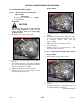
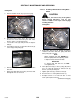
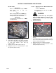
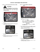
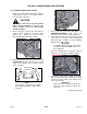
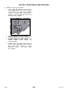
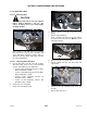
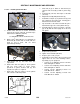
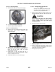
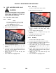
Table Of Contents
- 169000_RevF - Final - A Series OM Cover MACDON for WEB.pdf
- 169000_RevF - A Series OM FINAL w DofC for WEB
- back page
- new cover_WEB.pdf
- toc
- Model and Serial Number
- 1Safety
- 2Definitions
- 3Component Identification
- 4Specifications
- 5Operation
- 5.1Owner/Operator Responsibilities
- 5.2Operational Safety
- 5.3Tractor Setup: Pull-Type
- 5.4Mower Conditioner / Tractor Hook-Up: Pull-Type
- 5.5Mower Conditioner / Tractor Unhook: Pull-Type
- 5.6Header Attachment: Self-Propelled
- 5.7Configure Reverser Valve Jumper Hose
- 5.8Header Detachment: Self Propelled
- 5.9Transporting Header/Mower Conditioner
- 5.10Break-In Period
- 5.11Preseason Check
- 5.12Daily Start-Up Check
- 5.13Shutdown Procedure
- 5.14Engaging the Power Take-Off (PTO): Pull-Type
- 5.15Lift Cylinder Lockouts
- 5.16Steering the Pull-Type Mower Conditioner
- 5.17Unplugging the Header/Mower Conditioner
- 5.17.1Unplugging Conditioner and Knife: Pull-Type
- 5.17.2Unplugging Conditioner: Self-Propelled
- 5.17.3Unplugging Conditioner and Knife: Self-Propelled
- 5.18Header Operation
- 5.18.1Lean Bar Position
- 5.18.2Auger Speed
- 5.18.3Reel Speed
- 5.18.4Auger Position
- 5.18.5Reel Position
- 5.18.6Adjusting Tine Aggressiveness
- 5.18.7Cutting Height
- 5.18.8Header Angle
- 5.18.9Flotation
- 5.18.10Adjusting Feed Pan and Rock Drop Tine Position
- 5.18.11Hay Conditioner
- 5.18.12Adjusting Roll Tension
- 5.18.13Forming Shields
- 5.18.14Tall Crop Dividers
- 5.18.15Ground Speed
- 5.18.16Grass Seed Windrowing
- 5.18.17Haying Tips
- 5.18.18Storage
- 6Maintenance and Servicing
- 6.1Preparation for Servicing
- 6.2Recommended Safety Procedures
- 6.3Maintenance Specifications
- 6.4Driveshields
- 6.5Lift Cylinder Lock-Outs
- 6.6Lubrication
- 6.7Hydraulics
- 6.8Knife and Knife Drive
- 6.8.1Replacing Knife Section
- 6.8.2Sickle Removal
- 6.8.3Installing Knife
- 6.8.4Sickle Head Bearing Removal
- 6.8.5Sickle Head Bearing Installation
- 6.8.6Spare Sickle
- 6.8.7Sickle Guards
- 6.8.8Sickle Hold-Downs
- 6.8.9Sickle Drive Belt: A30-S
- 6.8.10Sickle Drive Belts: A30-D
- 6.8.11Sickle Drive Belts: A40-D
- Adjusting Tension on Knife Drive Timing Belt – A40-D Left Side
- Adjusting Tension on Knife Drive Timing Belt – A40-D Left Side
- Removal: A40-D LH Sickle Drive Timing Belt
- Removal: A40-D LH Sickle Drive Timing Belt
- Installing Knife Drive Timing Belts – A40-D Left Side
- Installing Knife Drive Double V-Belts – A40-D Left Side
- Adjusting Tension on Knife Drive Belt – A40-D Right Side
- Removing Knife Drive Belt – A40-D Right Side
- Installing Knife Drive Belt – A40-D Right Side
- 6.8.12Sickle Drive Belt Timing Adjustment
- 6.8.13Knife Drive Box
- 6.9Reel Drive Belts: A30-S, A30-D
- 6.10Reel Tines and Tine Bar Bearings – A30-D
- 6.11Reel and Reel Drive: A30-S, A30-D
- 6.12Reel and Reel Drive: A40-D
- 6.13Auger and Auger Drive – A30-D
- 6.14Auger and Auger Drive – A40-D
- 6.15Conditioner
- 6.15.1Changing Gearbox Oil
- 6.15.2Removing Forming Shield
- 6.15.3Disassembling Forming Shield
- 6.15.4Assembling Forming Shield
- 5.Attach adjuster rods (B) to side deflectors (C) with lynch pin (A).
- 6.15.5Installing Forming Shield
- 6.15.6Hydraulic Drive Motor Removal: All Models
- 6.15.7Hydraulic Drive Motor Installation: All Models
- 6.15.8Gearbox Removal: A30-S
- 6.15.9Gearbox Installation: A30-S
- 6.15.10Gearbox Removal: A30-D
- 6.15.11Gearbox Installation: A30-D
- 6.15.12Gearbox Removal: A40-D
- 6.15.13Gearbox Installation: A40-D
- 6.16Wheels and Tires – A30-D
- 6.17Replacing Skid Shoe Wear Plate
- 6.18Gauge Rollers
- 6.19Maintaining Electrical System
- 6.20Maintenance Schedule
- 7Troubleshooting
- 8Options and Attachments
- 9Unloading and Assembly
- Model and Serial Number
- toc
SECTION 7 MAINTENANCE AND SERVICING
169000 136 Revision F
7.8.12.3 Installing Knife Drive Box
a. Position knife drive box as shown, and install
four bolts (A). Torque side bolts, and then torque
bottom bolts to 200 ft·lbf (270 Nm).
IMPORTANT
Use only Grade L9 bolts and flat washers.
b. Apply Loctite
®
#243 adhesive (or equivalent) in
two bands (B) around shaft as shown, with one
band at end of shaft, and one band
approximately mid-way.
c. Slide pitman arm (C) onto knife drive box
output shaft.
d. Rotate knife drive box pulley to ensure pitman
arm just clears frame to ensure proper
placement on splines. Remove arm (C), and
reposition on splines as required.
e. Rotate knife drive box pulley to locate pitman
arm at furthest outboard position.
f. Slide arm (C) up or down on shaft until it just
contacts knife head (D) (0.010 in. [0.25 mm])
gap.
g. Install bolt (E) and nut, and torque to 160 ft·lbf
(217 N·m).
h. Align knife head (D) with pitman arm (C).
i. Install knife head pin (F) in pitman arm (C) and
tap it down into the knife head, ensuring pin is
bottomed out in the knife head.
j. Tap underside of the knife head until the pin is
flush with the upper face of the pitman arm (C).
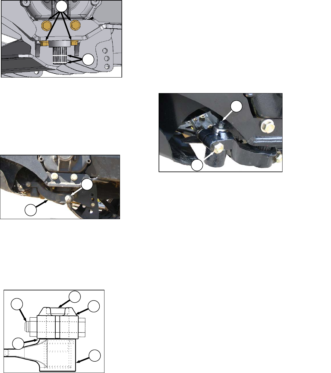
k. Carefully adjust to achieve a 0.010 in. (.25 mm)
gap at (G) with the knife laying flat on the first
few guards.
l. Replace bolt (H) and nut.
m. Tighten nut to 160 ft·lbf (220 N·m).
n. Replace grease zerk (J) in pin.
o. Install drive belt onto knife drive box pulley and
tighten. Refer to one of the following sections,
depending on your equipment:
• Section 7.8.9.1 Adjusting Tension: LH Knife
Drive Timing Belt – A30-D
• Section 7.8.9.4 Adjusting Tension: RH Knife
Drive Timing Belt – A30-D
• Section 7.8.10.1 Adjusting Tension: LH
Knife Drive Belts – A40-D
• Section 7.8.10.4 Adjusting Tension: RH
Knife Drive Belt – A40-D
A
B
C
E
J
H
C
F
H
G
D