
User Manual
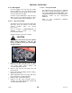
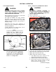
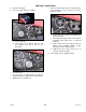
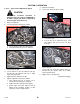
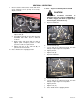
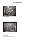
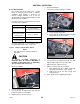
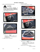
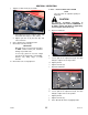
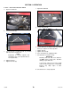
Table Of Contents
- 169000_RevF - Final - A Series OM Cover MACDON for WEB.pdf
- 169000_RevF - A Series OM FINAL w DofC for WEB
- back page
- new cover_WEB.pdf
- toc
- Model and Serial Number
- 1Safety
- 2Definitions
- 3Component Identification
- 4Specifications
- 5Operation
- 5.1Owner/Operator Responsibilities
- 5.2Operational Safety
- 5.3Tractor Setup: Pull-Type
- 5.4Mower Conditioner / Tractor Hook-Up: Pull-Type
- 5.5Mower Conditioner / Tractor Unhook: Pull-Type
- 5.6Header Attachment: Self-Propelled
- 5.7Configure Reverser Valve Jumper Hose
- 5.8Header Detachment: Self Propelled
- 5.9Transporting Header/Mower Conditioner
- 5.10Break-In Period
- 5.11Preseason Check
- 5.12Daily Start-Up Check
- 5.13Shutdown Procedure
- 5.14Engaging the Power Take-Off (PTO): Pull-Type
- 5.15Lift Cylinder Lockouts
- 5.16Steering the Pull-Type Mower Conditioner
- 5.17Unplugging the Header/Mower Conditioner
- 5.17.1Unplugging Conditioner and Knife: Pull-Type
- 5.17.2Unplugging Conditioner: Self-Propelled
- 5.17.3Unplugging Conditioner and Knife: Self-Propelled
- 5.18Header Operation
- 5.18.1Lean Bar Position
- 5.18.2Auger Speed
- 5.18.3Reel Speed
- 5.18.4Auger Position
- 5.18.5Reel Position
- 5.18.6Adjusting Tine Aggressiveness
- 5.18.7Cutting Height
- 5.18.8Header Angle
- 5.18.9Flotation
- 5.18.10Adjusting Feed Pan and Rock Drop Tine Position
- 5.18.11Hay Conditioner
- 5.18.12Adjusting Roll Tension
- 5.18.13Forming Shields
- 5.18.14Tall Crop Dividers
- 5.18.15Ground Speed
- 5.18.16Grass Seed Windrowing
- 5.18.17Haying Tips
- 5.18.18Storage
- 6Maintenance and Servicing
- 6.1Preparation for Servicing
- 6.2Recommended Safety Procedures
- 6.3Maintenance Specifications
- 6.4Driveshields
- 6.5Lift Cylinder Lock-Outs
- 6.6Lubrication
- 6.7Hydraulics
- 6.8Knife and Knife Drive
- 6.8.1Replacing Knife Section
- 6.8.2Sickle Removal
- 6.8.3Installing Knife
- 6.8.4Sickle Head Bearing Removal
- 6.8.5Sickle Head Bearing Installation
- 6.8.6Spare Sickle
- 6.8.7Sickle Guards
- 6.8.8Sickle Hold-Downs
- 6.8.9Sickle Drive Belt: A30-S
- 6.8.10Sickle Drive Belts: A30-D
- 6.8.11Sickle Drive Belts: A40-D
- Adjusting Tension on Knife Drive Timing Belt – A40-D Left Side
- Adjusting Tension on Knife Drive Timing Belt – A40-D Left Side
- Removal: A40-D LH Sickle Drive Timing Belt
- Removal: A40-D LH Sickle Drive Timing Belt
- Installing Knife Drive Timing Belts – A40-D Left Side
- Installing Knife Drive Double V-Belts – A40-D Left Side
- Adjusting Tension on Knife Drive Belt – A40-D Right Side
- Removing Knife Drive Belt – A40-D Right Side
- Installing Knife Drive Belt – A40-D Right Side
- 6.8.12Sickle Drive Belt Timing Adjustment
- 6.8.13Knife Drive Box
- 6.9Reel Drive Belts: A30-S, A30-D
- 6.10Reel Tines and Tine Bar Bearings – A30-D
- 6.11Reel and Reel Drive: A30-S, A30-D
- 6.12Reel and Reel Drive: A40-D
- 6.13Auger and Auger Drive – A30-D
- 6.14Auger and Auger Drive – A40-D
- 6.15Conditioner
- 6.15.1Changing Gearbox Oil
- 6.15.2Removing Forming Shield
- 6.15.3Disassembling Forming Shield
- 6.15.4Assembling Forming Shield
- 5.Attach adjuster rods (B) to side deflectors (C) with lynch pin (A).
- 6.15.5Installing Forming Shield
- 6.15.6Hydraulic Drive Motor Removal: All Models
- 6.15.7Hydraulic Drive Motor Installation: All Models
- 6.15.8Gearbox Removal: A30-S
- 6.15.9Gearbox Installation: A30-S
- 6.15.10Gearbox Removal: A30-D
- 6.15.11Gearbox Installation: A30-D
- 6.15.12Gearbox Removal: A40-D
- 6.15.13Gearbox Installation: A40-D
- 6.16Wheels and Tires – A30-D
- 6.17Replacing Skid Shoe Wear Plate
- 6.18Gauge Rollers
- 6.19Maintaining Electrical System
- 6.20Maintenance Schedule
- 7Troubleshooting
- 8Options and Attachments
- 9Unloading and Assembly
- Model and Serial Number
- toc

SECTION 6 OPERATION
169000 75 Revision F
6.17.5 Reel Position
Reel position has been found to be a critical
factor in achieving good results in adverse
conditions. Reel position is factory-set for
average straight standing crop. It can be
adjusted both vertically and horizontally (fore-aft)
for different crop conditions.
See table below for recommended reel position
in unusual crop conditions:
CROP CONDITION REEL POSITION
Crop Down or Lodged
Forward and Down
(Also Increase Reel Speed)
Wet or Dead Material
Collects On Cutterbar
and Plugs Knife.
Back and Down
(Close To Guards)
Short Crop Back
Thick Stemmed Or
Heavy Standing
Up And Forward
To make adjustments to reel position, refer to
the following Sections 6.17.5.1 to 6.17.5.4.
6.17.5.1 Reel Fore-Aft Position: A30-D
NOTE
The reel must be adjusted equally on
both sides.
CAUTION
To prevent accidental movement of
windrower, place all controls in NEUTRAL or
in PARK, engage park brake (if applicable),
shut off engine, and remove key.
a. Open LH endshield.
b. Loosen four nuts (A).
c. Loosen jam nut on adjuster bolt (B), and turn
bolt (B) to adjust fore-aft position.
d. Tighten jam nut, and four nuts (A).
e. Open RH endshield.
f. Loosen the reel drive chain (C) as follows:
1. Loosen nut (D) on sprocket.
2. Loosen jam nut on adjuster bolt (E), and turn
adjuster bolt (E) to loosen chain.
g. Loosen four nuts (F).
h. Loosen jam nut on adjuster bolt (G), and turn
adjuster bolt to adjust reel fore-aft position.
i. Tighten jam nut, and four nuts (F).
j. Tighten reel drive chain (C) as follows:
1. Turn adjuster bolt (E) to tighten chain until
total chain slack at (C) is 1/4 in. (6 mm).
2. Tighten jam nut at (E) and nut (D) and
recheck tension.
k. Close shields before engaging the header.
A
B
G
F
D
E
C