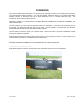
FOREWORD This manual contains safety information, set-up instructions, operating instructions, and maintenance procedures, for the Model MT8 Header Transporter. Your new MT8 Header Transporter allows you to transport MD draper headers (combine or windrower) with the M Series Windrower, truck, or combine (three-axle only). The Transporter can be towed at highway speeds. CAREFULLY READ ALL THE MATERIAL PROVIDED BEFORE ATTEMPTING TO UNLOAD, ASSEMBLE, OR USE THE MACHINE.
TABLE OF CONTENTS SECTION G ................................................GENERAL INFORMATION SECTION UA ................................................. SETUP INSTRUCTIONS SECTION OM .................................................
SECTION G – GENERAL INFORMATION SECTION G – GENERAL INFORMATION Section Contents ITEM DESCRIPTION PAGE G- 1 SAFETY .........................................................................................................................................................1 1.1 SAFETY ALERT SYMBOL ......................................................................................................................1 1.2 SIGNAL WORDS ............................................................................
SECTION G – GENERAL INFORMATION 1 SAFETY 1.1 1.2 SIGNAL WORDS Note the use of the signal words DANGER, WARNING, and CAUTION with safety messages. The appropriate signal word for each message has been selected using the following guidelines: SAFETY ALERT SYMBOL DANGER Indicates an imminently hazardous situation that, if not avoided, will result in death or serious injury. WARNING This safety alert symbol indicates important safety messages in this manual and on safety signs on the machine.
SECTION G – GENERAL INFORMATION 1.3.
SECTION G – GENERAL INFORMATION 1.4 SAFETY INSTRUCTIONS CAUTION The following are general farm safety precautions that should be part of your operating procedure for all types of machinery. • Provide a first-aid kit for use in case of emergencies. • Keep young children away from machinery at all times. • Be aware that accidents often happen when the operator is tired or in a hurry to get finished. Take the time to consider the safest way. Never ignore warning signs of fatigue.
SECTION G – GENERAL INFORMATION • Stop engine and remove key from ignition before leaving operator's seat for any reason. A child or even a pet could engage an idling machine. • Keep the area used for servicing machinery clean and dry. Wet or oily floors are slippery. Wet spots can be dangerous when working with electrical equipment. Be sure all electrical outlets and tools are properly grounded. • Use adequate light for the job at hand. • Keep machinery clean.
SECTION G – GENERAL INFORMATION 2 RECOMMENDED TORQUES 2.1 GENERAL The tables shown below give correct torque values for various bolts and capscrews. • • • • 2.2 Tighten all bolts to the torques specified in chart unless otherwise noted throughout this manual. Check tightness of bolts periodically, using bolt torque chart as a guide. Replace hardware with the same strength bolt. Torque figures are valid for non-greased or non-oiled threads and heads unless otherwise specified.
SECTION G – GENERAL INFORMATION 3 ENGLISH/METRIC EQUIVALENTS ENGLISH FACTOR SI UNITS (METRIC) acres x 0.4047 = hectares (ha) ft/min x 0.3048 = meters/min (m/min) ft/s x 0.3048 = meters/sec (m/s) gal (US) x 3.7854 = liters (L) US gal/min (gpm) x 3.7854 = liters/min (L/min) hp x 0.7457 = kilowatts (kW) in.3 x 16.3871 = cubic centimeters (cm3 or cc) lbf x 4.4482 = Newtons (N) lbf-ft or ft-lb x 1.3558 = Newton meters (N·m) lbf-in. or in-lbf x 0.
SECTION UA – UNLOADING AND SETUP Section Contents ITEM STEP 1. STEP 2. A. B. C. D. I. II. III. IV. V. STEP 3. STEP 4. A. B. C. D. E. F. STEP 5. Form 169365 DESCRIPTION PAGE UA- UNLOAD TRANSPORTER .............................................................................................................1 CONFIGURE THE TRANSPORTER ..............................................................................................2 ONE-AXLE ......................................................................
SECTION UA – UNLOADING AND SETUP STEP 1. UNLOAD TRANSPORTER g. Check for shipping damage and missing parts. CAUTION To avoid injury to bystanders from being struck by machinery, do not allow persons to stand in unloading area. CAUTION Equipment used for unloading must meet or exceed the requirements specified below. Using inadequate equipment may result in vehicle tipping or machine damage. LIFTING VEHICLE Min. Lifting 5000 lb. (2270 kg) Capacity * Min.
SECTION UA – UNLOADING AND SETUP STEP 2. CONFIGURE THE TRANSPORTER The transporter must be set up to carry a specific size and type of header. Refer to applicable section for each model of transporter. A. ONE-AXLE The one-axle transporter is designed to carry D Series 25 ft, and 30 ft windrower headers using a truck or an M Series windrower tractor.
SECTION UA – UNLOADING AND SETUP B. TWO-AXLE The two-axle transporter is designed to carry D Series and FD Series 25 ft, 30 ft, 35 ft, and 40 ft windrower and combine headers using a truck or an M Series windrower tractor. Determine the header that the transporter will carry and set up the transporter in accordance with the following table. Refer to paragraph D, TRANSPORTER ADJUSTMENT PROCEDURES for instructions.
SECTION UA – UNLOADING AND SETUP C. THREE-AXLE The three-axle transporter is designed to carry D Series and FD Series 25 ft, 30 ft, 35 ft, 40 ft, and 45 ft windrower and combine headers using either a truck, a M Series windrower tractor, or a combine. Determine the header that the transporter will carry and set up the transporter in accordance with the following table. Refer to paragraph D, TRANSPORTER ADJUSTMENT PROCEDURES, for adjustment instructions.
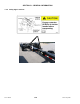
SECTION UA – UNLOADING AND SETUP II. MOVING REAR AXLES D. TRANSPORTER ADJUSTMENT PROCEDURES Two & Three Axle Transporter Only I. CUTTERBAR SUPPORTS A a. Loosen four lower bolts (A) on each axle support. C B a. Loosen four nuts on each support. b. Slide both supports to specified location (see previous page). NOTE Supports are joined by a tie angle and move together to maintain correct spacing. c. Re-tighten nuts. Ensure supports are evenly clamped onto main beam. B b.
SECTION UA – UNLOADING AND SETUP f. III. ADJUSTING AXLE SPACING – TWO & THREE AXLE Remove the four bolts (H) on both sides of rear H D a. Loosen four bolts (D) on underside of axle to be moved. E axle mount (J). J F g. Slide axle to new location and line up rear axle mounting holes (K). G K b. Loosen two bolts (E) on topside of forward axle. c. Loosen outer nuts on the forward axle adjuster rod (F). d.
SECTION UA – UNLOADING AND SETUP IV. BUMPER V. FRONT AND REAR SUPPORTS – TWO & THREE AXLE D A B C a. Loosen eight nuts (A) on bumper clamps. b. Slide bumper (B) to specified location (see previous page). c. Re-tighten nuts. Ensure nuts are evenly tightened. Form 169365 UA-7 FRONT SUPPORT SHOWN – REAR SUPPORT SIMILAR a. Loosen four bolts (C) on support (D). b. Slide support to desired location and retighten bolts. Ensure supports are evenly clamped onto main beam.
SECTION UA – UNLOADING AND SETUP STEP 3. SET UP COMBINE HITCH – THREE-AXLE ONLY E The combine hitch can be configured in two lengths depending on the combine and header size. The longer hitch is for combines where there is insufficient clearance between the rear of the combine and the header reel when rounding corners. CAUTION Towing the transporter with a truck when the combine hitch is installed is not recommended for highway travel.
SECTION UA – UNLOADING AND SETUP STEP 4. PRE-DELIVERY CHECK Perform the final checks and adjustments as listed on the "Pre-Delivery Checklist" (yellow sheet attached to back of this instruction) to ensure the machine is field-ready. Refer to the pages for detailed instructions as indicated on the checklist. The completed checklist should be retained either by the operator or the dealer. b. Drive slowly forward and apply brakes. Observe if electric brakes on transporter are operational. c.
SECTION OM – OPERATOR’S INSTRUCTIONS Section Contents ITEM DESCRIPTION PAGE OM1 COMPONENT IDENTIFICATION..................................................................................................................3 2 SPECIFICATIONS AND WEIGHT DATA ......................................................................................................4 2.1 SPECIFICATIONS ...................................................................................................................................4 2.
SECTION OM – OPERATOR’S MANUAL 4.3.3 Tires ..........................................................................................................................................34 4.3.3.1 Inflation ....................................................................................................................................................34 4.3.3.2 Wear ................................................................................................................................................
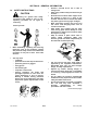
SECTION OM – OPERATOR’S MANUAL 1 COMPONENT IDENTIFICATION GUIDE CUTTERBAR SUPPORT HEADER LEG SUPPORT COMBINE HITCH CUTTERBAR TIE-DOWN BUMPER BREAKAWAY SYSTEM BATTERY TRACTOR/TRUCK HITCH MANUAL CASE BREAKAWAY SWITCH CUTTERBAR TIE-DOWN THREE-AXLE TRANSPORTER CUTTERBAR SUPPORT HEADER LEG SUPPORT BREAKAWAY SWITCH LIGHTBAR HEIGHT ADJUSTABLE PINTLE HITCH CUTTERBAR TIE-DOWN ONE AND TWO-AXLE TRANSPORTER Form # 169365 OM-3 Issue – May 2008
SECTION OM – OPERATOR’S MANUAL 2 SPECIFICATIONS AND WEIGHT DATA 2.1 SPECIFICATIONS ITEM AXLES MAX GROSS TRANSPORT WEIGHT LENGTH SPECIFICATION MT8-1 MT8-2 One Two Three 8000 lb (3620 kg) 12000 lb (5430 kg) 14000 lb (6335 kg) 467 in. (11866 mm) WEIGHT 2613 lb (1182 kg) MINIMUM HITCH LOAD 2000 lb (905 kg) 3255 lb (1473 kg) 3755 lb (1699 kg) 3000 lb (1375 kg) <100 lb.
SECTION OM – OPERATOR’S MANUAL 2.2 TRANSPORTER WEIGHT AND TONGUE WEIGHT DATA IMPORTANT: Weights are estimated and owner should check transporter weight when loaded.
SECTION OM – OPERATOR’S MANUAL 3 OPERATION 3.1 OWNER/OPERATOR RESPONSIBILITIES • CAUTION • • • • • • • 3.2 • • It is your responsibility to read and understand this manual completely before operating the mower conditioner. Contact your dealer if an instruction is not clear to you. Follow all safety messages in the manual and on safety signs on the machine. Remember that YOU are the key to safety. Good safety practices protect you and the people around you.
SECTION OM – OPERATOR’S MANUAL 3.4 TOWING ONE-AXLE AND TWOAXLE TRANSPORTERS WITH M SERIES WINDROWER TRACTOR b. Start tractor and lower windrower lift legs fully and approach hitch. c. Line up legs with pockets in hitch and drive forward until legs fully engage hitch. The one-axle and two-axle MT8 Header Transporters can be towed with the MacDon M Series Windrower Tractor provided that the MacDon Transporter Adapter Hitch (B5247) is attached to the tractor.
SECTION OM – OPERATOR’S MANUAL 3.4.2 Hookup to Windrower Adapter Hitch i. a. Open pintle on adapter hitch. b. Start tractor and activate header lift cylinders on tractor to lower tractor hitch. c. Slowly approach transporter hitch with tractor and line up pintle with hitch ring on transporter. d. Activate header lift cylinders on tractor until pintle engages hitch ring on transporter. Raise slightly to take weight of the hitch jack. e. Stop tractor engine and remove key.
SECTION OM – OPERATOR’S MANUAL 3.4.3 Unhook From Windrower Adapter Hitch g. Disconnect breakaway switch lanyard from windrower hitch. a. Stop tractor engine and remove key. b. Block the transporter wheels to prevent transporter from moving. h. Disconnect electrical plug on windrower hitch. i. Disengage tractor lift cylinder locks. j. Start tractor engine and activate header lift cylinders to lower the hitch and disengage pintle ring on transporter. c.
SECTION OM – OPERATOR’S MANUAL g. Stop engine and remove key. k. Start tractor and back away from hitch. l. Re-install clevis pins into hitch boots. h. Disconnect wiring harness at tractor. i. Remove safety chain from tractor and store on hitch. j. Remove clevis pins from tractor legs and set aside.
SECTION OM – OPERATOR’S MANUAL 3.5 TOWING ONE-AXLE AND TWOAXLE TRANSPORTERS WITH TRUCK b. Open pintle and lower transporter hitch onto truck hitch with jack. CAUTION • To avoid bodily injury and/or machine damage caused by loss of control: • Check tire condition and pressure prior to transporting. • Connect hitch to towing vehicle with a proper hitch pin with a spring locking pin or other suitable fastener. • Attach hitch chain to towing vehicle.
SECTION OM – OPERATOR’S MANUAL f. Check that transporter lights and brakes are functioning. 3.5.2 Unhooking from Truck a. Park transporter on level ground. b. Shutoff truck engine and remove key. c. Block the transporter wheels. g. Attach breakaway lanyard to truck hitch. d. Disconnect electrical plug from truck and store on transporter. e. Remove safety chains and breakaway switch lanyard from truck and store on transporter. f. Remove lynch pin from pintle and open pintle. g.
SECTION OM – OPERATOR’S MANUAL 3.6 TOWING THREE-AXLE TRANSPORTER WITH M SERIES WINDROWER TRACTOR 3.6.1 d. Slowly approach transporter hitch with tractor and line up pintle with hitch ring on transporter. e. Stop tractor engine and remove key. f. Lift transporter hitch onto tractor pintle hitch. Transporter Hookup to Windrower Adapter Hitch CAUTION Significant weight transfer to tractor is required for steering and braking in transport. See tractor operators manual. g.
SECTION OM – OPERATOR’S MANUAL IMPORTANT If transporter is being moved without a header on it, do not re-install pins in weight transfer assembly. Store pins in holes in frame. f. Disconnect wiring harness at tractor. g. Remove safety chain from tractor and store on hitch. k. If header is on transporter, re-insert pins and washers in slotted holes weight transfer assembly. l. Start tractor and raise header lift legs to full height (towing mode). m. Stop tractor engine and remove key. n.
SECTION OM – OPERATOR’S MANUAL 3.6.3 Windrower Hookup to Adapter Hitch on Transporter Refer to paragraph 3.4.1 Attaching Adapter Hitch to Windrower Tractor. 3.6.4 Transporter Unhook From Windrower Adapter Hitch a. Stop tractor engine and remove key. b. Block the transporter wheels to prevent transporter from moving. c. Disengage header lift cylinder stops. d. Start tractor and activate header lift cylinders to lower hitch to ground. h.
SECTION OM – OPERATOR’S MANUAL 3.7 TOWING THREE-AXLE TRANSPORTER WITH COMBINE Only a three-axle transporter can be towed with a combine when equipped with the combine towing hitch assembly. 3.7.1 Hookup to Combine a. If combine hitch not already installed, refer to SECTION UA. UNLOADING AND SETUP, Step 3. Set Up Combine Hitch. IMPORTANT Ensure hitch allows sufficient clearance between combine and header reel. Adjust hitch if required. Refer to SECTION UA, Step 3. Set Up Combine Hitch. 4.
SECTION OM – OPERATOR’S MANUAL NOTE Receptacle on combine must be a seven circuit RV type connector. FRONT VIEW – COVER OPEN IMPORTANT Center pin must not be energized. i. j. Attach breakaway switch lanyard to combine. Remove blocks from transporter wheels if applicable. 3.7.2 Unhook From Combine a. b. c. d. Park transporter on level ground. Shutoff combine engine and remove key. Block the transporter wheels. Disconnect breakaway switch lanyard from combine. e.
SECTION OM – OPERATOR’S MANUAL 3.8 TOWING THREE-AXLE TRANSPORTER WITH TRUCK CAUTION Ensure towing vehicle is capable of handling transporter tongue weight and gross weight to ensure adequate braking performance and control. 3.8.1 Hookup to Truck a. Refer to paragraph 2.1 TRANSPORTER WEIGHT AND TONGUE WEIGHT DATA for transporter gross weights and tongue weights. b. Back up truck to align pintle with transporter hitch. c. Shut off truck engine and remove key.
SECTION OM – OPERATOR’S MANUAL 3.9 LOADING D SERIES WINDROWER HEADER ONTO TRANSPORTER a. Set up transporter to suit your header. Refer to Step 2. Configuring The Transporter in SECTION UA. UNLOADING AND SETUP. b. Block the transporter wheels. 3.9.1 Prepare the Header a. Raise the stabilizer wheels on header as follows: C E d. If loading header for the first time, remove the two leg guides and hardware that are secured to the transporter left center support. Discard bolt and nut. e.
SECTION OM – OPERATOR’S MANUAL 3.9.2 Prepare the Transporter 3.9.3 Loading Procedure a. Disengage header lift cylinder stops and start windrower. b. Approach transporter from left hand side, lining up the mid-point of the header (center-link) with the mid-point of the two center supports on the transporter. a. Ensure both cutterbar tie-downs on transporter are in the down position and the transporter is cleared of tools or other debris that may damage the header.
SECTION OM – OPERATOR’S MANUAL IMPORTANT Header should rest firmly in and against the support pockets. g. Lower reel fully and retract to aft position. h. Shutdown windrower and remove key. i. Disconnect reel and header drive hydraulics and store on tractor. Refer to header operator’s manual. j. Disengage header float springs and disconnect center link. Refer to tractor operator’s manual. c. Slowly continue forward until the guards touch the white plastic stops on the transporter.
SECTION OM – OPERATOR’S MANUAL b. Position hook onto cutterbar lower edge. Pull lever to lock hook onto cutterbar. The tiedown is an over-center locking system and should require a firm pull to lock the hook. d. Re-install lynch pin in lever to lock into position. e. If the cutterbar tie-down does not latch properly, adjust as follows: 1. Check that header is properly positioned on transporter. 3. Back-off the two nuts below pivot with the lever in the up position. 4.
SECTION OM – OPERATOR’S MANUAL 3.9.5 Attach Header Anchor Chain a. If first use, undo bolt to remove retaining plate at end of chain. b. Install retaining plate in keyhole slot in header RH leg with bolt removed in previous step. Do not fully tighten as plate must be able to swivel. c. Swivel retaining plate and install chain in keyhole slot. Tighten bolt on plate to secure chain in slot.
SECTION OM – OPERATOR’S MANUAL 3.10 UNLOADING D SERIES WINDROWER HEADER a. Block the transporter wheels. f. Remove pins from header boots. b. Loosen bolt on anchor chain retaining plate and swivel plate off chain. c. Remove chain from slot. g. Rotate latch on centerlink to down position. d. Remove lynch pins from both cutterbar tiedowns and push levers down to disengage hooks from cutterbar. h. Approach header with windrower tractor and line up lift legs with header boots. i.
SECTION OM – OPERATOR’S MANUAL j. Connect center link as follows: MECHANICAL LINK – M150 1. Loosen nut and rotate barrel to adjust length so that link lines up with header bracket. 2. Install pin and secure with cotter pin. 3. Tighten nut against barrel. A slight tap with a hammer is sufficient. HYDRAULIC LINK – M200 STD, M150 OPTION 1. Activate header tilt cylinder switches in tractor to position center link cylinder so that it can connect to header. n.
SECTION OM – OPERATOR’S MANUAL 3.11 LOADING D AND FD SERIES COMBINE HEADER a. Set up transporter to suit your header. Refer to Step 2. Configuring The Transporter in SECTION UA. UNLOADING AND SETUP. b. Block the transporter wheels. 3.11.1 Prepare the Header and Transporter a. Raise the stabilizer wheels on header as follows: C E B A d. If loading header for the first time, remove the two leg guides and hardware that are secured to the transporter center support. Discard bolt and nut. e.
SECTION OM – OPERATOR’S MANUAL f. Locate leg guides on bolts and secure with nuts. NOTE Orange or red marking tape on the transporter frame identifies the mid-point between the center cutterbar supports. Tape may need to be relocated depending on header configuration. Refer to SECTION UA. Step 2. Configuring the Transporter. g. Ensure both cutterbar tie-downs on transporter are in the down position and the transporter is cleared of tools or other debris that may damage the header.
SECTION OM – OPERATOR’S MANUAL d. Slowly lower header onto transporter cutterbar supports. RIGID HEADER – LH SUPPORT e. Back up slightly until cutterbar guard tips approximately line up with the top plate on the cutterbar support. f. Continue to lower header until leg guides contact supports at rear of header and the header is resting fully on the transporter. IMPORTANT Header should rest firmly in and against the support pockets. RIGID HEADER – RH SUPPORT g. Detach header/adapter from combine.
SECTION OM – OPERATOR’S MANUAL 3.12 UNLOADING D AND FD SERIES COMBINE HEADER a. Block the transporter wheels. e. Leave lever in lowered position and store lynch pin in hole provided on lever. f. Attach combine to header/adapter. Refer to CA20 Combine Adapter Operator’s Manual. g. Activate header lift cylinders on combine to lift header off transporter. h. Back slowly away from transporter. b. Loosen bolt on anchor chain retaining plate and swivel plate off chain. c. Remove chain from slot. i. j.
SECTION OM – OPERATOR’S MANUAL 3.13 ATTACHING/DETACHING CA20 COMBINE ADAPTER 3.14 STORAGE Do the following at the end of each operating season: a. Clean the transporter thoroughly. CAUTION b. c. The combine and CA20 Combine Adapter may be detached from the header and then reattached with the header loaded on the MT8 transporter. Refer to the CA20 Combine Adapter Operator’s Manual for instructions. d. e. f. g.
SECTION OM – OPERATOR’S MANUAL 4 MAINTENANCE 4.1 RECOMMENDED SAFETY PROCEDURES • Park on level surface when possible. Block wheels securely if windrower is parked on an incline. • Follow all safety procedures in Section G, Paragraph 1, Safety Instructions. 4.2 LUBRICATING THE TRANSPORTER 4.2.1 Lubricants LUBRICANT Grease 4.2.2 SPEC SAE MultiPurpose. DESCRIPTION High Temp. Extreme Pressure (EP). 0-1% Max Molybdenum Disulphide (NLGI Grade 2). Lithium Complex Base.
SECTION OM – OPERATOR’S MANUAL 4.3 4.3.2 WHEELS AND TIRES DANGER DANGER Stop engine and remove key from ignition before leaving operator's seat for any reason. A child or even a pet could engage an idling machine. Stop engine and remove key from ignition before leaving operator's seat for any reason. A child or even a pet could engage an idling machine. 4.3.1 4.3.2.1 Removal Wheel Nuts IMPORTANT If transporter is not attached to towing vehicle, block transporter wheels to prevent movement.
SECTION OM – OPERATOR’S MANUAL c. Operate jack to raise wheel off ground. d. Remove wheel nuts and remove wheel. 4.3.2.2 Installation CAUTION When installing wheel be sure to use the holes that are countersunk to match nut profile. The uncountersunk holes do not seat the nuts correctly. IMPORTANT Be sure valve stem (A) points away from wheel support. a. Position wheel on spindle and install nuts. Partially tighten. b. Remove blocks or stand, and lower jack until tire contacts the ground. 1 6 3 4 2 5 c.
SECTION OM – OPERATOR’S MANUAL 4.3.3 Tires WARNING • • • • • • • • • • • • • 4.3.3.2 Wear a. Inspect tires as follows and in accordance with Maintenance Schedule. See paragraph 4.5. Service tires safely. WEAR PATTERN A tire can explode during inflation and cause serious injury or death. Do not stand over tire. Use a clip-on chuck and extension hose. Never increase air pressure beyond 40 psi (276 kPa) to seat the bead on the rim. Replace the tire if it has a defect.
SECTION OM – OPERATOR’S MANUAL 4.4 4.4.1 ELECTRICAL 4.4.1.4 License Plate Light Lights b. Use electrical tape and wire clips as required to prevent wires from dragging or rubbing. c. Keep lights clean and replace burnt bulbs. Refer to Parts Catalog. 4.4.1.1 Tail/Brake/Signal Replacement a. Loosen screw and pull off cover. b. Replace light bulb. c. Reinstall cover and tighten screw. 4.4.2 Electric Brakes 4.4.2.
SECTION OM – OPERATOR’S MANUAL 4.4.2.3 Breakaway Battery a. Remove four screws and two nuts in battery case cover. b. Pull off cover slowly as battery is not supported in case and may fall out. RED BLACK c. Check voltage across terminals with a voltmeter. It should read 12 volts. d. To replace battery, pull off spade type connectors from battery terminals and remove battery. e. Position new battery in case and connect blue wire to red terminal and the white wire to the black terminal.
SECTION OM – OPERATOR’S MANUAL 4.5 frame, e.g. "3 Months or 3000 Miles", service the machine at whichever interval is reached first. MAINTENANCE SCHEDULE The following maintenance schedule is a listing of periodic maintenance procedures, organized by service intervals. Regular maintenance is the best insurance against early wear and untimely breakdowns. Following this schedule will increase machine life. For detailed instructions, refer to the specific headings in this manual.
SECTION OM – OPERATOR’S MANUAL MAINTENANCE RECORD ACTION: 9 - Check 6 - Lubricate S - Change ↔ - Adjust Approximate Mileage Date Serviced By FIRST USE EVERY USE 9 Breakaway Switch Operational 9 Brakes Operational Refer to Paragraph 3.3, FIRST USE for checklist. NOTE: A RECORD OF DAILY MAINTENANCE IS NOT NORMALLY REQUIRED BUT IS AT THE OWNER/OPERATOR’S DISCRETION.
SECTION OM – OPERATOR’S MANUAL 5 TROUBLESHOOTING SYMPTOM Noisy Brakes Locking Brakes Transporter Pulls To One Side Brakes Dragging No Brakes PROBLEM PARAGRAPH SOLUTION Under Adjustment Adjust. * Broken Brake Components Replace Components. * Incorrect Brake Components Install Correct Components. * Loose, Bent, Or Broken Brake Components. Replace Components. * Faulty Controller. Test And Correct. * Insufficient Wheel Load. Adjust System Resistor And Synchronize. * Under Adjustment.
SECTION OM – OPERATOR’S MANUAL SYMPTOM Weak Brakes Harsh Brakes Surging Brakes Intermittent Brakes Brake/Signal Lights Not Working Breakaway System Not Working PROBLEM PARAGRAPH SOLUTION Brake Adjustment Not Correct. Adjust. * Corroded Connections. Clean And Correct Cause Of Corrosion. - Excessively Worn Brake Linings. Replace Shoe And Lining. * Incorrect Lining. Install Correct Shoe And Lining. * Grease Or Oil On Lining Or Magnets. Repair Grease Seal. Clean Or Replace Linings.
NOTES Form # 169365 OM-41 Issue – May 2008