
User guide

SECTION OM – OPERATOR’S MANUAL
Form # 169365 OM-27 Issue – May 2008
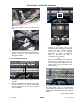
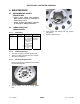
f. Locate leg guides on bolts and secure with
nuts.
g. Ensure both cutterbar tie-downs on transporter
are in the down position and the transporter is
cleared of tools or other debris that may
damage the header.
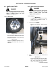
3.11.2 Loading Procedure
a. Disengage header lift cylinder stops and start
combine.
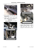
b. Approach transporter from left hand side, lining
up the mid-point of the header (center-link)
with the mid-point of the two center supports
on the transporter.
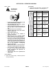
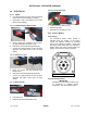
NOTE
Orange or red marking tape on the
transporter frame identifies the mid-point
between the center cutterbar supports.
Tape may need to be relocated
depending on header configuration.
Refer to SECTION UA. Step 2.
Configuring the Transporter.
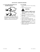
TIP
Mark the center guard with fluorescent
paint/marker or equivalent to assist in
lining up header with transporter. The
center guard is at the mid-point of the
header opening.
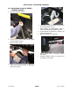
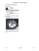
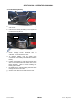
c. Slowly continue forward until the guards touch
the white plastic stops on the transporter.
Lower header as required so that the white
plastic stops remain visible from the operator’s
station.
(continued next page)