
Specification Sheet


Shenzhen Macroreer E-Business CO., LTD.
3/F, Building 57, DaYun Software Park, 20140806
HenGang ST, LongGang District, Shenzhen, P.R.C Zipcode: 518000 Ver.:1.0
Tel: +86-755-85210544 Fax: +86-755-85210544
http://www.macroreer.com Email:marketing@macroreer.com
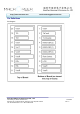
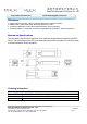
Pin Descriptions
Pin Signal Name Description Plug Seq. Notes
1 V
EET
Transmitter Ground 1
2 TX FAULT Transmitter Fault Indication 3 Note1
3 TX
DISABLE Transmitter Disable 3 Note2
4 MOD_DEF(2) SDA Serial Data Signal 3 Note3
5 MOD_DEF(1) SCL Serial Clock Signal 3 Note3
6 MOD_DEF(0) TTL Low 3 Note3
7 Rate Select Not Connected 3
8 LOS Loss of Signal 3 Note 4
9 V
EER
Receiver ground 1
10 V
EER
Receiver ground 1
11 V
EER
Receiver ground 1
12 RX- Inv. Received Data Out 3 Note 5
13 RX+ Received Data Out 3 Note 5
14 V
EER
Receiver ground 1
15 V
CCR
Receiver Power Supply 2
16 V
CCT
Transmitter Power Supply 2
17 V
EET
Transmitter Ground 1
18 TX+ Transmit Data In 3 Note 6
19 TX- Inv. Transmit Data In 3 Note 6
20 V
EET
Transmitter Ground 1
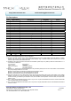
Notes:
Plug Seq.: Pin engagement sequence during hot plugging.
1) TX Fault is an open collector output, which should be pulled up with a 4.7k~10kΩ resistor on the host board to a voltage
between 2.0V and Vcc+0.3V. Logic 0 indicates normal operation; logic 1 indicates a laser fault of some kind. In the low
state, the output will be pulled to less than 0.8V.
2) TX Disable is an input that is used to shut down the transmitter optical output. It is pulled up within the module with a 4.7 ¨C
10 K resistor. Its states are:
Low (0 to 0.8V): Transmitter on
(>0.8, < 2.0V): Undefined
High (2.0 to 3.465V): Transmitter Disabled
Open: Transmitter Disabled
3) Mod-Def 0,1,2. These are the module definition pins. They should be pulled up with a 4.7K to 10K resistor on the host board.
The pull-up voltage shall be VccT or VccR
Mod-Def 0 is grounded by the module to indicate that the module is present
Mod-Def 1 is the clock line of two wire serial interface for serial ID
Mod-Def 2 is the data line of two wire serial interface for serial ID
4) LOS (Loss of Signal) is an open collector/drain output, which should be pulled up with a 4.7K to 10K resistor. Pull up voltage
between 2.0V and VccT, R+0.3V. When high, this output indicates the received optical power is below the worst-case
receiver sensitivity (as defined by the standard in use). Low indicates normal operation. In the low state, the output will be
pulled to <0.8V.
5) RD-/+: These are the differential receiver outputs. They are AC coupled 100 differential lines which should be terminated
with 100 (differential) at the user SERDES.
6) TD-/+: These are the differential transmitter inputs. They are AC-coupled, differential lines with 100 differential terminations
inside the module.