
User Manual

7/9/2013 CLUTCH_FLEXCOUPL_AIR_HD_MANUAL Page 4 of 4
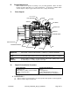
DISASSEMBLY (continued)
(3) Remove air cylinder with bearing from drive hub. The air cylinder bearing is a slide fit
on the drive hub and is affixed to the drive hub with a thin coating of Loctite
®.
You may
need to strike the hub, or an object inserted in the hub with a rubber mallet or similar
soft face hammer, while pulling the cylinder upwards to break the
Loctite
®
seal.
(4) Remove inner retainer ring from the drive hub.
(5) Remove sub-assembly consisting of the piston, bearing & cone. The disc package
(consisting of friction discs, drive discs & springs) will now be accessible. Note that the
first drive disc contains a milled hole. It is important that this disc is returned to the
top during reassembly to line up with the screw in the cone.
B. FRICTION DISC & SPRING REPLACEMENT
(1) Remove the drive discs, springs and friction discs.
(2) Drive discs should be clean, dry and free of burrs or nicks.
(3) Reassemble drive & friction disc section according to reference drawing using new
friction discs, springs and iron drive discs as necessary.
(4) Assure that gear tooth drive discs move freely on the drive hub and that the gear tooth
friction disc discs move freely in the ring gear.
C. O-RING REPLACEMENT
(1) Separate cylinder and piston/bearing/cone sub-assembly taking care not to bend the
pins which connect them.
(2) Inspect O-ring seals. If worn, replace using new O-rings that have been lubricated with
an O-ring lubricant such as Dow Corning
®
#
4 Compound or equivalent.
(3) A very thin coat of O-ring lubricant should also be applied to the inner walls of the
cylinder.
D. REASSEMBLY
(1) Place the piston/bearing/cone sub-assembly over drive hub making sure the screw
head in the cone is inserted in the corresponding hole milled in the drive disc. This
prevents the cone from skidding on the drive disc.
(2) Replace the inner retainer ring on the drive hub.
(3) Inspect the inside diameter of the bearing in the air cylinder. If Loctite
®
residue is
present, gently scrape and assure that the surface is clean.
(4) Place a small amount (dab) of grease (Mantek
®
Elite Red or equivalent) on the pins
that connect the air cylinder and piston.
(5) Apply a thin coat of Loctite
®
#609 retainer compound to the inside diameter of the
bearing (applying excessive Loctite
®
will make future disassembly more difficult), then
slide the air cylinder/bearing sub-assembly over the drive hub making sure the pins of
the cone are aligned with the holes in the cylinder.
(6) Make sure that all components are well seated and replace the outer retainer ring.
(7) See “Clutch Installation” portion of these instructions for the proper procedure for
reinstalling the clutch.
Technical assistance is available by contacting Mach III Clutch, Inc.
Mach III Product Warranty
http://www.machiii.com/Resources/Warranty-Info.asp
Mach III Clutch, Inc.
101 Cummings Drive ● Walton, KY 41094
Toll free 866.291.0849 ● International 859.291.0849 ● Fax 859.655.8362
info@machiii.com ● engineering@machiii.com ● www.machiii.com