Mother Board PT88BSPRO User's Manual Intel LGA775 Processor Motherboard VIA PT880PRO + VIA 8237 NO. G03PT88BPR207 Revision 2.
Table of Content Manual Revision History................................................................................................................................ii Copyright Announcement ..............................................................................................................................ii Trademarks Notice .........................................................................................................................................ii Safety Instructions ...........
Manual Revision History Revision Manual Revision History Date of Release Rev 2.0 First Edition copy of Mother Boards adopts VIA Chipsets: VIA PT880PRO and VIA VT8237 2005/08/17 Copyright Announcement COPYRIGHT OF THIS MANUAL BELONGS TO THE MANUFACTURER. NO PART OF THIS MANUAL, INCLUDING THE PRODUCTS AND SOFTWARE DESCRIBED IN IT MAY BE REPRODUCED, TRANSMITTED OR TRANSLATED INTO ANY LANGUAGE IN ANY FORM OR BY ANY MEANS WITHOUT WRITTEN PERMISSION OF THE MANUFACTURER.
Safety Instructions 1. 2. 3. 4. 5. 6. 7. 8. 9. Please read these safety instructions carefully. Please keep this User‘s Manual for later reference. Please place the equipment on a reliable flat surface before installation. Make sure the voltage of the power source when you try to connect the equipment to the power outlet. All cautions and warnings on the equipment should be noted. Disconnect this equipment from connecter before inserting add-on interfaces or modules.
Packing Item Checklist 5 5 5 5 □ 5 Motherboard Cable for IDE/Floppy Cable for Serial ATA IDE Port CD for motherboard utilities Cable for USB Port 3/4 (Option) User’s Manual Intel Pentium 4 LGA775 Processor Thermal Solutions As processor technology pushes to faster speeds and higher performance, thermal management becomes increasingly crucial when building computer systems. Maintaining the proper thermal environment is key to reliable, long-term system operation.
Chapter 1 Introduction of PT88BSPRO Motherboard Thank you for purchasing the PT88BSPRO which provide extremely performance and meet future specification demand. PT88BSPRO series motherboards are adopted with advanced technologies to deliver the extremely performance for Intel Pentium 4 Northwood/ Hyper-Threading/ Prescott LGA775 processors. The motherboard also feature AGP 8X/ PCI-Express x4 mode , Serial ATA RAID0, 1, USB 2.
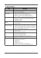
1-1.1 Special Features of motherboard CPU Thermal Throttling Technology---(The CPU Overheat Protection Technology) To prevent the increasing heat from damage of CPU or accidental shutdown while at high workload, the CPU Thermal Throttling Technology will force CPU to enter partially idle mode from 87.5% to 12.5% according to preset CPU operating temperature in BIOS (from 40℃ to 90 ℃).
1-2 Specification Spec Design Chipset CPU Socket Memory Socket Expansion Slot & Headers Integrate IDE and Serial ATA RAID On board LAN Audio BIOS Multi I/O ∗ ∗ ∗ ∗ ∗ ∗ ∗ ∗ ∗ ∗ ∗ ∗ ∗ ∗ ∗ ∗ ∗ ∗ ∗ ∗ ∗ ∗ ∗ ∗ ∗ ∗ ∗ Description ATX form factor 4 layers PCB size: 30.5x22.0cm VIA PT880PRO North Bridge Chipset VIA VT8237 South Bridge Support Intel Pentium 4 LGA775 package utilizes Flip-Chip Pin Grid Array (FC-PGA4) package processor Support 3.2G∼3.
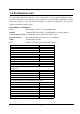
1-3 Performance List The following performance data list is the testing result of some popular benchmark testing programs. These data are just referred by users, and there is no responsibility for different testing data values gotten by users (the different Hardware & Software configuration will result in different benchmark testing results.) Performance Test Report Intel Pentium 4 LGA775 3.
1-4 Layout Diagram & Jumper Setting Line-OUT Line-IN Surrback LAN PRINT PS/2 Mouse PS/2 Keyboard COM1 COM2 USB2 USB GEN/LFE MIC-IN SURROUND CPU Socket PS2 KB/Mouse Port PC99 Back Panel ATX 12V Power Connector DDR DIMM X4 Audio Connector CPU FAN USB Port SFAN1 USB Port/LAN Connector ATX Power Connector VIA PT880PRO Chip KB/MS/USB Power ON Jumper (JP1) AGP 4X/8X Slot VIA VT6103 LAN PHY chip PCI EXPRESSx16 VIA VT8237 Chip ITE IT8705 I/O Chip ATA 133 IDE Connector Serial-ATA Connector (SATA1
Jumpers Jumper JBAT JP1 Name Description CMOS RAM Clear Keyboard/USB Power On Enable/Disabled USB Power On Enable/Disabled JP3 Page 3-pin Block 3-pin Block P.6 P.7 3-pin Block P.
Chapter 2 Hardware installation 2-1 Pre-Hardware installation Before starting to use the computer with the motherboard installed the components on it, please make sure complete the following steps: 1. To verify the jumper settings of your motherboard 2. To install the CPU and Cooling Kits 3. To install the system memory 4. To install the expansion cards 5. To connect with ribbon cables, panel wires, and power supply 6. To setup BIOS 7.
(2) Keyboard/USB Power On function Enabled/Disabled: JP1, JP3 When setting Enabled you can using keyboard by key in password/USB to power on system.
2-3-2 About INTEL PENTIUM 4 775PIN CPU This motherboard provides a 775-pin surface mount, LGA775 Land Grid Array socket, referred to as the LGA775 socket supports Intel Pentium 4 processor in the 775 Pin package utilizes Flip-Chip Land Grid Array (FC-LGA4) package technology. The CPU that comes with the motherboard should have a cooling FAN attached to prevent overheating. If this is not the case, then purchase a correct cooling FAN before you turn on your system.
2-3-3 LGA 775 CPU Installation Guide Socket Preparation 1. Opening the socket: Note: Apply pressure to the corner with right hand thumb while opening/closing the load lever, otherwise lever can bounce back like a “mouse trap” and WILL cause bent contacts (when loaded) Socket Load Plate Open 1. Disengage Load Lever by depressing down and out on the hook to clear retention tab 2. Rotate Load Lever to fully open position at approximately 135degrees 3.
3. Visually inspect for bent contacts (Recommend at least 1stpass visual inspection) NOTE: Refer to the Handling and Inspection Module for 1stand 2ndpass inspection details. NOTE: Glove images are for illustrative purposes only. Please consult local safety guidelines for specific requirements NOTE: Recommend not to hold the load plate as a lever, instead hold at tab with left hand, removing the PnP cap with right hand 775-land LGA Package Insertion 1.
775-Land Package Removal 1. Open the Load Plate/Lever with both hands: With left hand index finger and thumb to support the load plate edge, engage PnP cap with right hand thumb and peel the cap from LGA775 Socket while pressing on center of PnP cap to assist in removal. 2. Pick up 775-land LGA package: By Vacuum Pen: Place a minimum 9-mm cup at approximately the center of IHS. Recommend not to place Vacuum Pen on IHS edge. Risk of dropping and causing bent contact.
5. Visually inspect socket contact array 1. First Pass Inspection i. Scan socket contact array at varying angles noting the presence of any foreign material ii. If foreign material can’t be blown off by compressed air, or mechanical damage (Mode1 or 4) observed, reject the motherboard for further evaluation or socket replacement. 2. Second Pass Inspection i. Repeat 2 more times to sight down the rows and columns from each of the 4 sides of the socket to ensure all contacts within the array are inspected ii.
Apply Thermal Interface Material NOTE: Thermal Solutions that come with IntelR boxed processor use pre-applied thermal interface material and not grease. 3. Remove Heat Sink (HS) from packaging media 4. Place HS onto the LGA775 Socket • Ensure fan cables are oriented on side closest to fan header • Align Fasteners with MB through-holes 5.
Intel Reference Thermal Solution Disassembly 1. Rotate fastener cap. turn to un-lock 2. Pull up fastener cap to un-seat 12 1. Disconnect fan cable from motherboard header 2. Turn fastener caps (4) counter-clock wise 90degrees to the un-locked position • A flat-bladed screwdriver may be used if required 3. Pull up on fastener caps to unseat 4. Manually remove HS with gentle twist motion. 5. To re-assemble the HS, reset the fastener caps to their original position with the slot perpendicular to the HS.
6 5 IPA Dry 1. Remove the heatsink from the socket 2. Gently push loose thermal interface material (TIM) to center of processor (pictures 2 and 3) 3. Remove pieces with dry cloth (picture 4) 4. Wipe with dry, lint-free cloth to remove most of the material (picture 5) 5. Wet another lint-free cloth with isopropyl alcohol (IPA) and wipe to clean remaining material (picture 6) 6. Be careful to remove material from gaps between processor and load plate 7.
1 Dry 2 Replacing Damaged Fasteners • To prevent damage, avoid setting the thermal solution with the prongs down − Set on heatsink side or with fan down • The plastic fasteners on the heatsink can be replaced. − Use Shop Intel to order spare fasteners − http://www.shop-intel.com • To remove a damaged fastener Note: Protective gloves are not required for this procedure − Rotate the black pin counterclockwise until it “snaps”.
Damaged. Attempts to straighten not recommended Tilt to remove Replacing Fasteners • − − − − To replace the fastener Start with the white prong Note the “keying” notch feature Tilt the prong to insert into the heatsink leg.
Click Note: The black pin and white prong will only “snap” on in one orientation − Check to ensure the black pin is rotated properly for installation with the slot perpendicular to the heatsink 2-4 To install the system memory This motherboard provides four 184-pin DDR DUAL INLINE MEMORY MODULES (DIMM) sites for DDR memory expansion available from minimum memory size of 128MB to maximum memory size of 4.0GB DDR SDRAM.
DIMM4 (BANK6+BANK7) DIMM3 (BANK4+BANK5) DIMM2 (BANK2+BANK3) DIMM1 (BANK0+BANK1) Figure 2-4 DIMM1 & DIMM3: Dual Channel 1 DIMM2 & DIMM4: Dual Channel 2 NOTE! When you install DIMM module fully into the DIMM socket the eject tab should be locked into the DIMM module very firmly and fit into its indention on both sides. WARNING! For the DDR SDRAM CLOCK is set at 200MHz, use only DDR400-compliant DDR Modules.
2-5-2 Assigning IRQs For Expansion Card Some expansion cards need to assign an IRQ address to operate. Generally speaking, an IRQ address must exclusively assign to one use only. With standard factory design, there are 16 IRQs available, but most of them are already in use.
2-5-4 AGP Slot/ PCI Express Slot This motherboard provides both AGP Slot and PCI-Express Slot, support the 4X/8X AGP VGA card and PCI-Express x16 VGA card.
2-6 Connectors and pin headers 2-6-1 Connectors (1) Power Connector (24-pin block) : ATXPWR24P ATX Power Supply connector. This is a new defined 24-pins connector that usually comes with ATX case. The ATX Power Supply allows to use soft power on momentary switch that connect from the front panel switch to 2-pins Power On jumper pole on the motherboard.
(3) PS/2 Mouse & PS/2 Keyboard Connector: PS2KBMS1 The connectors for PS/2 keyboard and PS/2 Mouse. (4) USB Port connector: USB, USB1 The connectors are 4-pin connector that connect USB devices to the system board (5) LAN Port connector: LAN This connector is standard RJ45 connector for Network (6) Parallel Port connector (25-pin D-sub connector): PARALLEL (7) Serial Port connector: COM1, COM2 The connectors is 9-pin Male connector that connect serial devices to the system board.
(10) Primary IDE Connector (40-pin block): IDE1 This connector supports the provided IDE hard disk ribbon cable. After connecting the single plug end to motherboard, connect the two plugs at other end to your hard disk(s). If you install two hard disks, you must configure the second drive to Slave mode by setting its jumpers accordingly. Please refer to the documentation of your hard disk for the jumper settings.
2-6-2 Pin headers AUDIO AUD_RET_L AUD_GND AUD_VCC AUD_RET_R (1) Line-Out, MIC Header (9-pin): AUDIO This header connect to Front Panel Line-out, MIC connector with cable. 2 10 Pin 1 AUD_MIC AUD_MIC_BIAS AUD_FPOUT_R HP_ON AUD_FPOUT_L 9 Line-Out, MIC Headers VCC -DATA +DATA GND OC VCC +DATA GND +DATA GND Pin 1 VCC USB3 Pin 1 -DATA USB2 -DATA +DATA GND OC VCC -DATA (2) USB Port Headers (9-pin) : USB2, USB3 These headers are used for connecting the additional USB port plug.
GND PWRBTN PWRBTN PWR LED VCC5 JW FP PWRLED PWRLED Pin 1 SPEAK VCC5 HDDLE GND RSTSW NC HDLED RESET GND VCC5 Pin 1 SPKR NC Pin 1 System Case Connections (8) FAN Headers (4-pin) : CPUFAN FAN Headers (3-pin) : SFAN1, SFAN2 These connectors support cooling fans of 350mA (4.2 Watts) or less, depending on the fan manufacturer, the wire and plug may be different. The red wire should be positive, while the black should be ground.
2-7 Starting up your computer 1. After all connection are ready, close your computer case cover. 2. Be sure all the switches are off, and check that the power supply input voltage is set to proper position, usually in-put voltage is 220V∼240V or 110V∼120V depending on your country’s voltage used. 3. Connect the power supply cord into the power supply located on the back of your system case according to your system user’s manual. 4. Turn on your peripherals as following order: a. Your monitor. b.
Chapter 3 Introducing BIOS Settings The BIOS is a program located on a Flash Memory of the motherboard. Using this program as a bridge between motherboard and operating system. When the computer starting to work, the BIOS program gain control. The BIOS first operates an auto-diagnostic test called POST (power on self test) for all the necessary hardware, it detects the entire hardware device and configures the parameters of the hardware synchronization.
3-2 Getting Help Main Menu The on-line description of the highlighted setup function is displayed at the bottom of the screen. Status Page Setup Menu/Option Page Setup Menu Press F1 to pop up a small help window that describes the appropriate keys to use and the possible selections for the highlighted item. To exit the Help Window, press . 3-3 The Main Menu Once you enter Award BIOS CMOS Setup Utility, the Main Menu (Figure 3-1) will appear on the screen.
Standard CMOS Features Use this Menu for basic system configurations. Advanced BIOS Features Use this menu to set the Advanced Features available on your system. Advanced Chipset Features Use this menu to change the values in the chipset registers and optimize your system’s performance. Integrated Peripherals Use this menu to specify your settings for integrated peripherals. Power Management Setup Use this menu to specify your settings for power management.
3-4 Standard CMOS Features The items in Standard CMOS Setup Menu are divided into several categories. Each category includes no, one or more than one setup items. Use the arrow keys to highlight the item and then use the or keys to select the value you want in each item.
3-5 Advanced BIOS Features Phoenix – AwardBIOS CMOS Setup Utility Advanced BIOS Features Anti-Virus Protection Limit CPUID MaxVal C1E Function > HardDisk Boot Priority CPU L1 & L2 Cache Hyper-Threading Technology CPU L2 Cache ECC Checking Quick Power On Self Test First Boot Device Second Boot Device Third Boot Device Boot other Device Boot Up Floppy Seek Boot Up NumLock Status Typematic Rate Setting x Typematic Rate (Chars/Sec) x Typematic Delay (Msec) Security Option MPS Version Control For OS OS Select fo
Quick Power On Self-Test This category speeds up Power On Self Test (POST) after you power on the computer. If this is set to Enabled. BIOS will shorten or skip some check items during POST. Enabled (default) Enable quick POST Disabled Normal POST First/Second/Third/Fourth Boot Device The BIOS attempts to load the operating system from the devices in the sequence selected in these items. The settings are Floppy, LS/ZIP, HDD-0/HDD-1/HDD-3, SCSI, CDROM, LAD and Disabled.
3-6 Advanced Chipset Features The Advanced Chipset Features Setup option is used to change the values of the chipset registers. These registers control most of the system options in the computer.
3-6-1 DRAM Timing Settings Phoenix – AwardBIOS CMOS Setup Utility DRAM Timing Setting x x x x x Auto Configuration RAS Active Time RAS to CAS Delay RAS Percharge Time DRAM CAS Latency Time Bank Interleave DRAM Command Rate By SPD 8T 3T 3T 2.
3-6-3 PCI Timing Settings Phoenix – AwardBIOS CMOS Setup Utility PCI Timing Settings PCI Master 0 WS Write PCI Delay Transaction Vlink Mode Selection Vlink 8X Support Enabled Enabled By Auto Enabled Item Help Menu Level >> ↑↓→← Move Enter:Select +/-/PU/PD:Value F10:Save ESC:Exit F1:General Help F5:Previous Values F6:Optimized Defaults F7:Standard Defaults PCI Delay Transaction The chipset has an embedded 32-bit posted write buffer to support delay transactions cycles.
3-7-1 Onboard IDE Function Phoenix – AwardBIOS CMOS Setup Utility Onboard IDE Function OnChip SATA OnChip IDE Channel0 Primary Master PIO Primary Slave PIO Primary Master UDMA Primary Slave UDMA OnChip IDE Channel1 Secondary Master PIO Secondary Slave PIO Secondary Master UDMA Secondary Slave UDMA IDE DMA Prefetch Access IDE Prefetch Mode Enabled Enabled Auto Auto Auto Auto Enabled Auto Auto Auto Auto Enabled Enabled IDE HDD Block Mode Enabled Item Help Menu Level >> ↑↓→← Move Enter:Select +/-/PU/PD:
3-7-2 Onboard Device Function Phoenix – AwardBIOS CMOS Setup Utility Onboard Device Function Onboard VIA Device Onboard LAN Boot ROM VIA LAN BootROM Boot Option VIA LAN BootROM PXERPL Option Current VIA MAC Address is VIA MAC Address Input AC97 Audio Device USB Host Controller USB 2.
Onboard FDC Controller Select Enabled if your system has a floppy disk controller (FDD) installed on the system board and you wish to use it. If you install add-on FDC or the system has no floppy drive, select Disabled in this field. The settings are: Enabled and Disabled. Onboard Serial Port 1/Port 2 Select an address and corresponding interrupt for the first and the second serial ports. settings are: 3F8/IRQ4, 2E8/IRQ3, 3E8/IRQ4, 2F8/IRQ3, Disabled, Auto.
3-8 Power Management Setup The Power Management Setup allows you to configure your system to most effectively save energy saving while operating in a manner consistent with your own style of computer use.
3-8-1 IRQ/Event Activity Detect Phoenix – AwardBIOS CMOS Setup Utility IRQ/Event Activity Detect VGA LPT & COM HDD & FDD PCI Master PS2KB Wakeup Select PS2KB Wakeup from S3/S4/S5 Wake-Up on GPI Wake-Up on PCI Card Modem Ring Resume RTC Alarm Resume x Date of Month Alarm x Time (hh:mm:ss) > IRQs Activity Monitoring OFF LPT/COM ON OFF Hot key Disabled Disabled Disabled Disabled Disabled 0 0 : 0 : 0 Press Enter Item Help Menu Level >> ↑↓→← Move Enter:Select +/-/PU/PD:Value F10:Save ESC:Exit F1:General Hel
3-9 Miscellaneous Control This section is for setting CPU Frequency/Voltage Control.
3-10 PC Health Status This section shows the Status of you CPU, Fan, Warning for overall system status. This is only available if there is Hardware Monitor onboard. Phoenix – AwardBIOS CMOS Setup Utility PC Health Status Show PC Health in Post Current CPU Temperature Current SYS Temperature Current CPUFAN Speed Current SYSFAN Speed Current SYSFAN1 Speed Vcore VDIMM VCC3.3 +5V +12V 3.3VSB(V) VBAT 5VSB(V) Enabled 70°C/158°F 30°C/ 86°F 0 RPM 4687 RPM 0 RPM 1.35V 2.54V 3.20V 5.16V 12.04V 3.19V 1.89V 5.
CPU Thermal Throttling Temp This item allows you to activate the CPU Thermal Throttling function when the CPU temperature is over the value which you set to low down the CPU temperature when at high workload to protect processor from damage or accidental shutdown.
3-13 Password Settings Phoenix – AwardBIOS CMOS Setup Utility Password Settings Set Supervisor Password Set User Password Press Enter Press Enter Item Help Menu Level > ↑↓→← Move Enter:Select +/-/PU/PD:Value F10:Save ESC:Exit F1:General Help F5:Previous Values F6:Optimized Defaults F7:Standard Defaults You can set either supervisor or user password, or both of them. The differences are: Supervisor password: Can enter and change the options of the setup menus.
3-14 Load Standard/Optimized Defaults Load Standard Defaults When you press on this item, you get confirmation dialog box with a message similar to: Load Standard Defaults (Y/N)? N Pressing loads the BIOS default values for the most stable, minimal-performance system operations.
Chapter 4 DRIVER & FREE PROGRAM INSTALLATION Check your package and there is A MAGIC INSTALL CD included. This CD consists of all DRIVERS you need and some free application programs and utility programs. In addition, this CD also include an auto detect software which can tell you which hardware is installed, and which DRIVERS needed so that your system can function properly. We call this auto detect software MAGIC INSTALL.
4-1 VIA 4IN1 Install VIA Service Pack 4 IN 1 Driver * The path of the file is X:\VIA\DRIVER\SETUP.EXE VIA ATAPI VENDOR SUPPORT DRIVER IS USED TO FIXED COMPATIBILITY IDE : ISSUE FOR IDE DEVICES VIA AGPVXD DRIVER IS TO BE INSTALLED, IF YOU ARE USING AN AGP AGPVXD : VGA CARD, VIAGART.
7. Click NEXT to Install VIA AGP VXD Driver 8. Click NEXT to Install VIA IRQ Routing Mini port Driver 9. Click Finish to restart computer 4-2 SOUND install ALC Audio Codec Driver 1. Click SOUND when MAGIC INSTALL MENU appears 2.
3. Click FINISH and restart your computer 4. Manual Sound Effect Setting 5. Speaker configuration setting 6. SPDIF out setting 4-3 LAN Install VIA LAN Controller Driver The VIA 10/100Mb PCI Ethernet Adapter Driver path is X:\VIA\LANDRV 1. Click LAN when Magic Install Menu appear 2.
4-4 1. USB2.0 Install VIA USB2.0 DEVICE DRIVER Click USB2.0 when MAGIC INSTALL MENU Appear 2. When USB2.0 Setup Program Appear, Click NEXT Note: Please Install Microsoft Service Pack 1 in Windows XP OS Before you Install VIA USB2.0 Device Driver. Please Install Microsoft Service Pack 4 in Windows 2000 OS Before you Install VIA USB2.0 Device Driver. The Path of the file is X:\VIA\VIAUSB20\SETUP.EXE 4-5 SATA Install VIA Serial ATA 1. Click SATA when MAGIC INSTALL MENU appears 2.
3. When license agreement appear, choose I agree and click NEXT 4. Select you want to install driver 5. Review install driver and utility component, then click NEXT 6. Click FINISH and restart your computer Making SATA HDD driver diskette before Install WindowsXP/2000 If you only have Serial ATA HDDs on your system, before you install the Windows XP or Windows 2000, you will need to make a SATA HDD driver diskette before you start to install the Operating System.
4-6 PC-CILLIN Install PC-CILLIN 2005 Anti-virus program 1. Click PC-CILLIN when MAGIC INSTALL MENU appear 2. Please select “Install program” when the "Trend Micro internet security" installshield wizard windows appear 3. Click NEXT and Enter your Customer Information, Click NEXT or choose Change to change the path for the file to be stored 4. Please select install “FULL” function or install “Antivirus software” only 5. We suggest to use “Recommend configuration”. 6.
4-7 PC-HEALTH install ITE Smart Guardian utility The path of the file is X:\VIA\ITESMARTGD\SETUP.EXE (Support Windows 9X/ME/2K/NT/XP) 1. Click PC-Health when Magic Install Menu appears 2. Click Next , install ITE Smart Guardian utility 3. Click Finish , complete install ITE Smart 4. executing Program → ITE Smart Guardian , The Guardian utility ITE Smart Guardian auto detect system voltage, Fan speed and CPU/ SYSTEM Temperature.
4-8 HOW TO DISABLE ON-BOARD SOUND Enter BIOS SETUP choose INTEGRATE PERIPHERALS choose ON-CHIP DEVICE FUNCTION choose AC97 SOUND DEVICE Disable on-board sound function by press PAGE DOWN KEY to Disable 4-9 Method 1. HOW TO UPDATE BIOS In DOS Mode STEP 1. Prepare a boot disc. (you may make one by click START click RUN type SYS A: click OK) STEP 2. Copy utility program to your boot disc. You may copy from DRIVER CD X:\FLASH\AWDFLASH.EXE or download from our web site. STEP 3.
4-10 Pro Magic Plus Function Introduction What’s Pro Magic Plus? Tired with reinstall OS each time when it doesn’t work? Does your computer often crash down or unable to work after installed new software? Have you had great loses and troubles because of computer problems? Still using time-consuming backup software that occupies lots of HD space? Pro Magic Plus- an instant system recovery software tailored to solve these problems for you. It combines various application tools (e.g.
NOTE: Functions of each version will differ from each other, and will be based on the function descriptions of each version.