OWN E R ’ S MAN U AL
DC16 Owner’s Manual Important Safety Instructions 1. Read these instructions. 18. NOTE: This equipment has been tested and found to comply with the limits for a Class B digital device, pursuant to part 15 of the FCC Rules. These limits are designed to provide reasonable protection against harmful interference in a residential installation.
DC16 Owner’s Manual Table of Contents Important Safety Instructions....................................................................................................... 2 Table Of Contents........................................................................................................................... 3 Chapter 1 : Welcome....................................................................................................................... 6 Chapter 2 : Getting Started..........................
DC16 Owner’s Manual Channel Screens Overview........................................................................................................................ 25 Channel Displays and Encoders................................................................................................ 25 Channel Editing Page Buttons.................................................................................................. 26 Banking Group Selector..............................................................
DC16 Owner’s Manual Snapshot Control........................................................................................................................................ 54 Display........................................................................................................................................ 54 Arrow Buttons............................................................................................................................ 54 RECALL Button..................................
DC16 Owner’s Manual Chapter 1 : Welcome Hello everyone! This is the DC16 Owner’s Manual...we hope you like it! Instead of one massive document containing detailed information about the hardware and software, we have divided them into separate manuals. Simply decide if you need assistance with the DC16 control surface hardware or Master Fader iOS control app and dive on in. The water here is warm and crystal clear.
DC16 Owner’s Manual Chapter 2 : Getting Started The following instructions will help you get your system set up and started in no time. You should only have to follow these instructions once and then you will be well on your way to a beautiful future of mixing. This upgrade can take up to 30 minutes, so follow these steps well in advance of a show, demo or other event. 1. Be sure to perform a full System Backup of Master Fader – Tools > Settings > System Backup. 2.
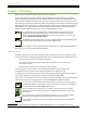
DC16 Owner’s Manual (B) – Push the encoder in to select the DL32R. DC16 Connect to Mixer: Initializing... DL32R Refresh Mixer list Select Do it! Exit (C) – We’ll assume here that you will only be using a single DC16 at this time. Therefore, push the encoder in to select the FOH slot. DC16 Select DL32R connection FOH MON 3 4 slot empty empty empty empty Initializing... (D) – Once selected, DC16 will ask if you want to auto route Dante and DL32R.
DC16 Owner’s Manual 6. Turn the powered speakers (or amplifiers) on. 7. Connect an iPad to the iPad Control Port (located on the rear panel of DC16), launch the Master Fader app and connect to the DL32R / DC16 (as explained in the Master Fader Reference Guide ‘Devices’ section). 8. Set the volume of the source input, starting with channel one. 9. Adjust the channel's mic pre gain until the meters on that channel bounce between green and yellow. Engage phantom power if needed. 10.
DC16 Owner’s Manual Chapter 3 : A Closer Look at Slots and Dante Introduction In the previous chapter – Chapter 2 : Getting Started – we suggested selecting the FOH slot and auto-routing Dante.
DC16 Owner’s Manual Dante Dante – Digital Audio Network Through Ethernet – is the de facto standard in digital audio networking, delivering unmatched audio quality, extremely flexible routing and offers significant cost savings compared to traditional analog cable runs. The dual Dante ports allow daisy chaining and the dedicated Wi-Fi control port eliminates the need for an Ethernet switch in many situations.
DC16 Owner’s Manual So what’s really happening when you to choose to auto-route Dante? Let’s take a look at the under-the-hood changes taking place. As mentioned on the previous page auto-routing Dante “...configures the headphones, monitors, talkback and stereo playback and recording signals between the DL32R and DC16.” In short, you’re setting up a monitor mix FOR DC16 FROM DL32R. That is, what goes TO the DC16 headphone and monitor outputs is a mirror image of the DL32R headphones and monitor outputs.
DC16 Owner’s Manual The same exact thing shown on the previous page is outlined below now. Instead of the signal flow, though, it’s the Dante routing.
DC16 Owner’s Manual Now let’s take a look at Master Fader’s I/O Patch. For reference, the right-hand side of the signal flow – the DL32R side – may be seen below-left. As stated previously, the first thing routed in Master Fader’s I/O Patch is Input A (below-right). Again, Dante 30-31 is routed to Return 3-4 and Dante 32 is routed to Talkback.
DC16 Owner’s Manual Other Dante Routing Perhaps you recall that Dante 1-29 had no default patching. That’s because they are available for a variety of other purposes. You have multiple controllable options for routing and where they’re routed. We have addressed three possible ways to record shows, including: • DL32R USB output to hard drive • DL32R USB output to laptop • Stereo recording to iPad But there is a fourth option, though, which is Dante routing to other recording equipment.
DC16 Owner’s Manual The second step is to set up Dante routing via Master Fader [Tools > I/O Patch > Dante]. We already set up Dante with a 1-to-1 setup, so we need to do the same in Master Fader. See below. All Dante to Mic Pre settings are patched, but a single screen shot showing all is impossible. Basically what we’re doing here is sending outputs 1-28 of the DL32R – since 29-32 have already been auto-routed – to whatever your routing choice may be...a Dante Virtual Sound Card, for example.
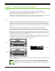
DC16 Owner’s Manual Chapter 4 : DC16 Front and Rear Panels Front Panel Introduction From left to right, the front panel of each DC16 is outfitted with a phones jack and...that’s it! Let’s take a look at the phones jack then move on to the rear panel before it’s too late. Phones Jack This 1/4" TRS connector supplies the output to stereo headphones. The volume is controlled with the Phones knob located in the upper-right corner of the top panel of the DC16.
DC16 Owner’s Manual Rear Panel Introduction From left to right, the rear panel of each DC16 is outfitted with a talkback mic input jack, an 1/8" stereo input jack, 1/4" L/R monitor output jacks, a 1/4" footswitch jack, two Dante I/O jacks, a force update button, a network connector for Wi-Fi control, three USB ports for iPad control and charging, a power connector and power switch and last but not least...a 4-pin input jack for a lamp.
DC16 Owner’s Manual TRS jacks and plugs are used for balanced signals and stereo headphones and are wired as follows: RING SLEEVE 1/4" TRS Balanced Mono Wiring: Sleeve = Shield Tip = Hot (+) Ring = Cold (–) SLEEVE RING TIP TIP RING TIP SLEEVE To connect unbalanced lines to these inputs, use a 1/4" mono (TS) phone plug, wired as follows: SLEEVE SLEEVE 1/4" TS Unbalanced Mono Wiring: Sleeve = Shield Tip = Hot (+) TIP TIP TIP SLEEVE Unbalanced cables can be noisy.
DC16 Owner’s Manual Force Update Button The force update button is conveniently located between the Dante A / B and Network connectors. In a perfect world, this button would just sit there without a care in the world, umbrella drink in hand, beach, surf and sun on a daily basis. Continuing with this “perfect world” scenario, I would be right by the force update button (also without a care in the world, umbrella drink in hand, beach, surf and sun on a daily basis).
DC16 Owner’s Manual Power Connector Push the locking multi-pin connector (flat side up) of the power supply into the power connector of the control surface. Push the line cord securely into the power supply and plug the other end into a grounded AC outlet. These are included in the packaging. Make sure that the AC power is matched to the AC power indicated on the rear panel (below the power connector). Warning: Disconnecting the plug’s ground pin is dangerous.
DC16 Owner’s Manual Chapter 5 : DC16 Top Panel Top Panel Introduction From top to bottom and left to right, the top panel of each DC16 is outfitted with a bunch of knobs, switches, faders, screens, encoders and more. So much more, in fact, that we will call out and describe each one... but not here... and not left-to-right like we did with the front and rear panels. Rather, what you see below is an outline and order each section will be described.
DC16 Owner’s Manual Input Channels / Master Channel There are a total of 16 input channel strips and one master channel strip on DC16. From top to bottom each strip contains the following: • SEL (Select) Buttons A select button does exactly what it sounds like it does. It selects that input or output, readying it for immediate editing purposes.
DC16 Owner’s Manual • Gain Reduction LEDs The input gain reduction LEDs display the channel gain reduction from the gate and compressor, while the output gain reduction LEDs display the amount of gain reduction applied to the output by the compressor / limiter. Output channels do not contain gates. These LEDs display the sum of the total reduction applied by the gate and compressor [inputs, mono] and compressor / limiter [outputs, stereo].
DC16 Owner’s Manual Channel Screens Overview Lying horizontally above the fader strips are 17 channel displays and two Channel Editing Page buttons. The channel display on the far left is the selected channel display and does not have an encoder below it; the remaining 16 channel displays have encoders for parameter control. See below for image and descriptions.
R DC16 Owner’s Manual • Editing Page Buttons On the far right of the channel displays strip are two editing page buttons with one arrow pointing up and the other pointing down. These are for displaying additional parameters. For example, parametric EQ has a TON of parameters that may be edited, but there are only 16 channel displays with encoders. Simply push these buttons to view the other available parameters. These button LEDs are always illuminated when they are available for use.
DC16 Owner’s Manual Groups Selector The groups selector section – appropriately named “GROUPS” – is located on the left-hand side of DC16 just to the left of the faders. Here is where channel settings, view groups, mute groups, user-assignable controls, context-sensitive editing controls and more are displayed and edited. Also of notice are the eight unmarked buttons to the right of the groups displays. These are for selecting the corresponding group(s) as indicated in the displays.
DC16 Owner’s Manual If multiselect is ON – highlighted white with black text – multiple view groups may be selected simultaneously (except “ALL”). As seen below, if multiselect is OFF – not highlighted, white text – then only a single view group may be selected at a time. Customized View Groups Select ALL Break Song I Song II Song III Song IV Song V Multiselect Additionally, channels may be assigned (and unassigned) to view groups simply by utilizing the assign modifier button.
1 DC16 Owner’s Manual 2 • MUTE Group Button Mute groups allow you to quickly mute (and unmute) multiple channels and/or outputs. There are a multitude of possibilities in which to assign and enable mute groups: productions featuring a rotating 3 theater productions, a house of worship and more. It is also great for muting all inputs cast of musicians, during song breaks or in-between sets. Pressing the 4 MUTE button will present all mute groups in each of the four displays as noted below.
DC16 Owner’s Manual As seen below, if multiselect is ON – highlighted white with black text – multiple view groups may be selected simultaneously (except “NONE”). If multiselect is OFF – not highlighted, white text – then only a single mute group may be selected at a time. Additionally, channels may be assigned (and unassigned) to mute groups simply by utilizing the assign modifier button. More details in the “Modifiers” section.
DC16 Owner’s Manual Mix Selector The mix selector section – appropriately named “MIXES” – is located on the right-hand side of DC16 just to the right of the faders. This is the place to select between output mixes, cycle through the displayed outputs, display output masters, clear all engaged solos and engage the talkback mic. Also of notice are the eight unmarked buttons to the left of the mix displays. These are for selecting the corresponding output(s) as indicated in the displays.
DC16 Owner’s Manual As mentioned previously, you need to use the page buttons in order to view and select from other mixes. That said, let’s take a quick look at a description and other pertinent notes of the page buttons. • Page Buttons R These buttons shift the currently shown MIXES groups (mentioned on the previous page) up or down. LED status: The arrow button LEDs are always illuminated when they are available for use.
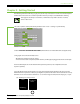
DC16 Owner’s Manual After pushing the page down button, the mixes will display A7-A14. This customization is also relatively simple. Here, the only changes made are A7-A12 were linked and named. A13 and A14 were also renamed, but left unlinked. All colors were left at their default except A9-A10. In addition to being linked and named, the color of A9-A10 was also changed from it’s default green to red.
DC16 Owner’s Manual Ok, we’re making progress! Push the page down button again to display the FX mixes. The customizations in this example are naming and coloring. As seen below, Rev1 retains the same purple color, but was renamed to its effect, Plate. Rev2 and Dly were renamed to reflect their effect, too – Spring and Tape Echo. However, their colors were changed from their default purple to yellow (Rev2, Spring) and light green (Dly Tape, Echo).
DC16 Owner’s Manual Things start to get a little interesting once we get to the subs. As before, push the page down button to display the subs mixes. The customizations in this example are linking, naming and coloring. As seen below, Sub1-Sub4 are linked. Sub1-Sub2 retains the same default blue color, but was renamed to “Kit”. The color of Sub3-Sub4, though, was changed from its default blue to orange. Additionally, it was renamed to “Choir”.
DC16 Owner’s Manual The VCAs work somewhat similarly to that of the subs. Let’s see how! Push the page down button to display the VCAs. The customizations in this example are naming and coloring. [VCAs cannot be linked]. VCA1 retains the same default green color, but was renamed to “Guitar”. The color of VCA2, though, was changed from its default green to orange. Additionally, it was renamed to “Horns”. Lastly, the color of VCA3 was changed from its default green to a pinkish-red.
DC16 Owner’s Manual Last up are the matrices. Push the page down button to display all six. The customizations in this example are naming and coloring. [Matrices may be linked, but aren’t in this example]. M1 retains the same default white color, but was renamed to “Lobby”. The color of M2, though, was changed from its default white to violet. Additionally, it was renamed to “Balcony”. When a matrix is selected, the DC16 will display all subgroups, LR and auxes.
Wedges In-ears DC16 Owner’s Manual • MAST(er) Button If the MAST button is engaged then you are out of MIXES mode and in MASTERS mode...and now we want that! [For reference, MIXES mode was just described on pages 31-37]. The MAST button is a fast, effective way to switch between the mix selector and masters. Pressing the MAST button will present all output masters in each of the four displays as seen below.
R DC16 Owner’s Manual L R Wedges X Whereas you’re able to raise and lower the inputs and outputs of the selected mix while in MIXES mode, no inputs are available when in MASTERS mode. MASTERS mode is strictly for raising and lowering the selected master [LR, aux, FX, subs, VCAs and/or matrix]. DC16 is smart, only recalling your specific mix selector and masters set up. In other words, any changes made in MASTERS mode will then be evident in MIXES mode upon your return.
DC16 Owner’s Manual Channel Editing The channel editing buttons are conveniently located in the upper-left corner of the DC16 to the left of the channel IDs and above the groups selector section. The channel editing buttons give you fast access to all of the channel processing. These buttons – in conjunction with the channel displays and editing encoders – open up a world of possibilities. Please read on...
DC16 Owner’s Manual • GAIN Button This button selects the mic pre gain of all channel inputs. Gain adjusts the input sensitivity of the mic and mic/line inputs. This allows signals from the outside world to be adjusted to run through each channel at optimal internal operating levels. The gain levels may then be changed by rotating the encoders below the channel displays. A visual representation may be seen on the DC16 channel displays and the input routing screens on Master Fader.
DC16 Owner’s Manual • HPF Button This button selects the HPF frequency of all inputs and outputs. High-pass filters are utilized to cut out low frequencies. The high-pass filter control adjusts the cut-off frequency for the filter. HPF levels may then be changed by rotating the encoders and turned on [green] or off [gray] by pushing the encoders below the channel displays. A visual representation may be seen on the DC16 channel displays and the channel’s EQ screens on Master Fader.
DC16 Owner’s Manual • SEND Button This button selects the sends of all inputs. This allows you to easily change the levels of each channel sent to auxes and FX. The send levels may then be changed by rotating the encoders below the channel displays. A visual representation may be seen on the DC16 channel displays and input routing view on Master Fader. The send ranges from Off to +10 dB. The send button’s LED illuminates white when engaged.
DC16 Owner’s Manual • PAN Button This button selects the pan and balance of all inputs and outputs. The pan / balance may then be changed by rotating the encoders below the channel displays. A visual representation may be seen at the bottom of the DC16 channel displays and on the pan screen of Master Fader. As seen in the image below, channel 1 is panned hard left, channel 2 is center panned and channel 3 is panned hard right.
DC16 Owner’s Manual That wraps up the ALL portion of channel editing meaning we’re on to the SELECTED portion of channel editing. As a reminder, SELECTED channel editing allows adjustment of the selected group of parameters for the SELECTED channel. Let’s take a look... • EQ Button This button selects and displays the EQ parameters of the selected channel for editing. There is a plethora of EQ-related information detailed in the Master Fader Reference Guide.
DC16 Owner’s Manual • GEQ Button This button selects and displays the GEQ parameters of the selected output for editing. [There is no GEQ on inputs]. GEQ is a great tool for really dialing in the response needed for a room or to squelch feedback from monitors. The GEQ parameters may then be changed by rotating the encoders below the channel displays. A visual representation may be seen on the DC16 channel displays and the GEQ screen on Master Fader.
DC16 Owner’s Manual • SENDS Button (ALT + GEQ) This button displays each channels’ send levels, allowing you to easily change the aux and FX levels of the selected input. The sends levels may then be changed by rotating the encoders below the channel displays. A visual representation may be seen on the DC16 channel displays and input routing view on Master Fader. The sends ranges from Off to +10 dB. 7 OH Kick 8 S Top 1 Rack OH 7 Tom Rack 5 dB OH 6 dB 7 8 -40.0 OFF -16.0 50L -18.
DC16 Owner’s Manual • DYN(amics) Button This button displays the gate and compressor controls of the selected input for editing. Gates are typically used to reduce leakage from open microphones. Signals below the threshold level are muted, while signals above the threshold get to pass through. Compressors are used to reduce or limit transient peaks in a signal. If the signal is too hot, the compressor turns it down; otherwise it leaves it alone.
5 DC16 Owner’s Manual • FX Button This button selects and displays the FX controls for the reverb and delay processors of the selected input for editing. There are two reverbs and one delay at your disposal; these may be fed from any combination of channels with dedicated FX sends. We follow standard FX send and return configuration, allowing you to easily adjust the FX in one convenient location for each selected channel.
DC16 Owner’s Manual Fat Channel The Fat Channel is conveniently located dead center of the DC16 above the channel IDs and in front of the center iPad. In addition to the fader controls, the Fat Channel is likely where you will spend the majority of time. Why? Well, because it contains access to the most frequently updated controls for the selected input or output channel, regardless of what channel editing button is currently engaged (see pages 40-49, 70-73).
DC16 Owner’s Manual • TRIM Encoder (ALT + GAIN) This encoder adjusts the level of the digital trim of the selected input. Trim is a digital level control at the top of the channel’s processing. It affects all input sources to the channel whether analog or digital and is used for adding or removing level to a channel before any of the channel processing. The trim ranges from –40 dB to +20 dB and adjusts in ±1 dB to ±2.5 dB increments.
DC16 Owner’s Manual • Four-band Parametric EQ Buttons and Encoders [GAIN, FREQ, Q] The four “BAND” buttons allow you to select which EQ band you want to update of the selected input or output. The currently selected band button LED illuminates white when engaged. One of these EQ button LEDs will always be illuminated, but never more than one. Once a band is selected, rotate the encoders located above these buttons to change the gain, frequency and Q (if applicable) of that band.
DC16 Owner’s Manual • COMP RATIO Encoder (ALT + COMP THRESH) This encoder adjusts the comp ratio of the selected input or output. The ratio is changed by rotating the encoder and the comp may be turned on [green] or off [white] by pushing the encoder. Ratio sets the amount of gain reduction applied as the signal exceeds the threshold level. The range of the ratio of the compressor varies from 1:1 to inf:1. The incremental adjustments are dependent on if the selected comp is modern or vintage.
LT * IT! OYZ DC16 Owner’s Manual Snapshot Control The snapshot control section – “SHOW” – is located in the upper-right corner of DC16 just below the three analog controls and above the mix selector – “MIXES”. Here you are able to easily view, select, recall and store snapshots. Let’s find out how! > 1 2 3 DEFAULT INTRO * RAWK IT! CRY BOYZ NEW...
2 3 RAWK IT! CRY BOYZ NEW... DC16 Owner’s Manual • RECALL Button This button recalls snapshots via DC16. Pressing the RECALL button once causes the button’s LED to flash red. In order to recall this snapshot, you will need to press the button a second time (within five seconds of the first press) to confirm the recall. After five seconds of inactivity, the store button’s LED reverts back to its solid red state.
DC16 Owner’s Manual Analog Controls These three analog controls (located in the upper-right corner of DC16) allow you to raise and lower the talkback, monitor and headphones levels. Because these are analog controls, they are NOT recallable. Analog Controls • TALKBACK Knob This knob controls the input level of the talkback mic with the gain ranging from a low of off (–∞) up to a maximum of +10 dB. The talkback output level is set up via Master Fader’s Quick Access Panel.
DC16 Owner’s Manual Modifiers The modifiers section is located on the left-hand side of DC16 just below the groups section. It consists of four buttons that are used to modify the functionality of other controls. These buttons are simply modifiers and won’t work on their own. Instead, they are to be used in conjunction with other buttons or encoders in order to update settings. We’ll go over each of the buttons starting at the left and head our way right.
DC16 Owner’s Manual • ASGN Button This button is used in conjunction with other buttons to adjust input and output assignments. There’s a lot of info here, so please pay attention! The button’s LED illuminates solid red when pressed and held, but another button must be pressed in order to enter what’s called “Assignment Mode”. When in assignment mode: (1) the ASGN button’s LED will flash red.
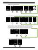
DC16 Owner’s Manual Assign Mode: View Group E Song IV Assign Mode: Mute Group 3 Song II Assign Mode: Talkback • ASGN + View Group – Pressing and holding the ASGN button while pressing one of the [Groups Selector] view groups buttons [view group A-F] puts the console into assignment mode for that view group.
DC16 Owner’s Manual Smart Bridge The Smart Bridge is where up to three iPads may be placed for easy viewing and charging purposes. More importanty, iPads placed on the Smart Bridge may be used for control and audio streaming where it automatically detects their presence and enables Following operation modes. Follow Mode is significant as it allows you to configure and integrate each iPad to behave automatically.
DC16 Owner’s Manual Listed below is a quick overview of what you can expect over the next few pages, starting at the top with iPad setup.
DC16 Owner’s Manual DC16 Slot: The DC16 Slot pull-down menu is where you select which DC16 you want the iPad to follow. In most cases this will either be FOH or MON, but there are two additional choices – slot 3 and slot 4. It should be noted that slot 3 and slot 4 are for more elaborate systems such as those requiring a broadcast desk or two FOH engineers. The DC16 slot is set up on a per iPad basis.
DC16 Owner’s Manual • Follow Mode As mentioned earlier, Follow Mode allows you to customize each iPad on the Smart Bridge to behave automatically.
DC16 Owner’s Manual Fixed View: Like the Current and History Follow Modes, Fixed View is somewhat self-explanatory. iPads that are set to Fixed Mode will stay on the view you desire regardless of the Follow Mode setting on the other iPads. While the view constantly changes on iPads set to Current and History Follow Modes, the view on iPads set to Fixed View won’t change at all...until you make the change on the actual iPad.
DC16 Owner’s Manual The fourth pull-down menu – Overview Selects Current – has two options: On [default] or Off. What this means is that when an iPad is displaying Overview, you can select whether or not any iPads following the current channel go to the selected input(s) or output(s) when touched on the Overview screen. This allows you to view all inputs and outputs (on the Overview screen), then quickly go to the channel(s) needing a quick EQ and/or dynamic adjustment.
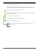
DC16 Owner’s Manual Examples of Follow Mode: Now that you know what Follow Mode is, let’s take a look at some use case examples: The most common setup I’ve seen (and used) is the following: iPad A – Current Selected Channel iPad B – 1st History Selected Channel iPad C – 2nd History Selected Channel B A C Here you have the iPad in the center slot – iPad A – displaying the current view of the currently selected channel.
DC16 Owner’s Manual At this point, it’s probably a good idea to mess around with these three settings in a variety of methods until you fully grasp what it does, how it works and what it can do for you and your needs. Once understood, we’ll move onto Fixed View Follow Mode [super-easy to master] and Advanced Follow Mode [not quite as easy to conceive, but we’ll get you dialed in!] The following is a common setup utilizing the Fixed View Follow Mode.
DC16 Owner’s Manual Having said that, the Product Manager and our road warriors prefer a similar setup, but ever-so-slightly different.
DC16 Owner’s Manual Perhaps the most common use of the Advanced settings that I’ve seen around the office and out in the field is what’s known as “The Fattest Channel”. For now, we’ll just look at the first three settings [Follow Selected Channel, View and Mix].
DC16 Owner’s Manual • SETUP Button (ALT + DYN) This button selects and displays the initial setup controls and a few other goodies! These settings are not stored as snapshots. They will remain where you leave them, regardless of the selected snapshot (including the default snapshot 0). They are actually stored in the DL32R for the associated slot. So if you change DC16s, the slot retains the settings and the new DC16 will come up just like the old one. More about slots below.
DC16 Owner’s Manual Screen Brightness: How bright do you want the channel displays? Press or rotate the encoder until you see the choice you prefer between: Low Mid High [Default] Sun – NYI – The “Sun” setting is not yet implemented, but will add a high contrast mode so the screen brightness is even more legible when the DC16 is used in direct sunlight at outdoor venues.
DC16 Owner’s Manual The channel displays on the second page, though, offer the following options: 5 Tom GAIN Auto return from selected channel editing Hide channel names in selected channel editing 20 sec OFF Calibrate Faders Do it! About Tell Me! Auto return from selected channel editing: This is a handy feature that allows you to stay on the most important – to you – ALL channel editing function after you’ve made some quick SELECTED channel edits.
DC16 Owner’s Manual Hide channel names in selected channel editing: By default, when a SELECTED channel editing mode is selected, the channel’s names and numbers are presented in the channel display along with the editing mode characteristics. However, if you would prefer the channel names and numbers not be there – only displaying the editing mode characteristics – simply change this setting to “On”.
DC16 Owner’s Manual Appendix A : Hookup Diagram Live Sound: House Engineer A B Wi-Fi CONTROL Here’s a pretty common setup utilizing the full Axis system. DC16 Front and Top Panels: * Three iPads placed on the Smart Bridge. * Pair of headphones connected to the phones jack. DC16 Rear Panel: * Mic connected to the Talkback jack. * Smart phone or MP3 player connected to the stereo input jack. * Pair of XR-Series monitors connected to the L/R monitor jacks.
DC16 Owner’s Manual Appendix B : Technical Information Specifications General Digital Sample Rate:..................................................................................................................................................................................................48 kHz A/D/A Bit Depth:...........................................................................................................................................................................................
DC16 Owner’s Manual Specifications Continued... Analog Monitor Outputs L/R Connectors:..................................................................................................................................................... 1/4" TRS Impedance Balanced . [Supports balanced / unbalanced operation] Output Impedance:................................................................................................................................................................. 240 .
DC16 Owner’s Manual Specifications Continued... Dante Connection:..................................................................................................................................................... 2x etherCon Gigabit Ethernet Sample Rate:..................................................................................................................................................................................................48 kHz Bit Depth:............................................
DC16 Owner’s Manual Specifications Continued... Power Power Consumption:............................................................................................................................................................................102 watts External Supply Power Requirements:........................................................................................................................ 100 VAC – 240 VAC, 50 – 60 Hz . Universal Supply Output Voltage:....................................
DC16 Owner’s Manual DC16 Dimensional Drawings 79
DC16 Owner’s Manual DC16 Dimensional Drawings Continued...
DC16 Owner’s Manual Appendix C : Service Information Troubleshooting If you think your DC16 has a problem, please check out the following troubleshooting tips and do your best to confirm the problem. Visit the Support section of our website (www.mackie.com/support) to get some ideas or contact our technical support heroes. You may find the answer to the problem without having to send your DC16 away.
DC16 Owner’s Manual Dante Difficulties? • We took time writing up a Dante Setup Guide. Check it out HERE1! • There is a massive amount of information on the Audinate website. Check it out HERE2! No Interwebs • Read the chapter titled “Wireless Setup” in the Master Fader Reference Guide. This section is very important and reading it cover-to-cover is the best troubleshooting.
DC16 Owner’s Manual Warranty Statement Please keep your sales receipt in a safe place. This Limited Product Warranty (“Product Warranty”) is provided by LOUD Technologies Inc. (“LOUD”) and is applicable to products purchased in the United States or Canada through a LOUD-authorized reseller or dealer. The Product Warranty will not extend to anyone other than the original purchaser of the product (hereinafter, “Customer,” “you” or “your”). For products purchased outside the U.S. or Canada, please visit www.