
User Manual
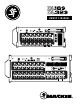

DL16S • DL32S Owner’s Manual
7
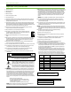
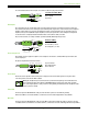
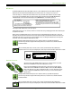
To connect unbalanced lines to these inputs, use a /4" mono (TS) phone plug, wired as follows:
/4" TS Unbalanced Mono Wiring:
Sleeve = Shield
Tip = Hot (+)
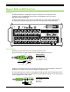
XLR Outputs
These male XLR connectors provide balanced line-level signals that represent the end of the mixer, where the signals enter
the real world. Connect these to line-level inputs of your main PA system, stage monitors, external eects devices, headphone
amplifiers, and/or whatever else you desire. The PA/monitor speaker system could either be passive (powered by external
amplifiers) and/or powered (with built-in power amplifiers). You may run separate mixes since all outputs are independent
of each other and are completely routable via the Master Fader control sofware. Pretty cool, huh?!
They are wired as follows, according to standards specified by the AES (Audio Engineering Society):
XLR Balanced Wiring:
Pin = Shield (ground)
Pin 2 = Positive (+ or hot)
Pin 3 = Negative (– or cold)
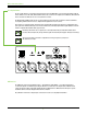
Phones Output Jack
This /4" TRS connector supplies the output to stereo headphones. The volume is controlled with the phones knob located
near the output jack.
The phones output follows standard conventions:
Tip = Lef channel
Ring = Right channel
Sleeve = Ground
Phones Knob
This knob is used to adjust the volume from the phones output jack, from o to maximum gain (max). The phones knob
is an analog control, and is therefore NOT recallable.
Warning: The headphone amp is loud and could cause permanent hearing damage. Even intermediate levels
may be painfully loud with some headphones. BE CAREFUL! Always turn the phones knob all the way down
before connecting headphones, soloing a channel or doing anything new that may aect the headphone volume.
Then turn it up slowly as you listen carefully.
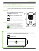
Power LED
For the most part, this LED will illuminate solid green when the mixer is powered on and funtioning normally.
However, this LED has several other identifiers, as well. Please refer to the table in Appendix D for all possibilities.
Wi-Fi LED
For the most part, this LED will illuminate solid green when Wi-Fi is functioning normally and a tablet or computer connection
is established. However, this LED has several other identifiers, as well. Please refer to the table in Appendix D for all possibilities.
SLEEVE
TIP
TIP
SLEEVE
TIP
SLEEVE
2
1
SHIELD
COLD
HOT
3
SHIELD
COLD
HOT
3
2
1
SLEEVE
TIP
SLEEVE
TIP
RING
RING
TIP
SLEEVERING