402-VLZ3 14-Channel Mic/Line Mixer OWNER’S MANUAL MIC 1 MIC 2 MIC PRE XDR MIC 4 MIC 3 MIC PRE XDR MIC PRE XDR MIC 5 MIC PRE XDR MIC 6 MIC PRE XDR LEFT/MONO RIGHT ALL BAL/UNBAL 1 MIC PRE XDR 2 BAL OR UNBAL LINE IN 1 BAL OR UNBAL LINE IN 2 LOW CUT 75 Hz 18dB/OCT U OO AUX U OO +15 U OO EQ +15 U -15 +15 U -15 -15 -15 +15 -15 -15 -15 AUX U OO OO EQ -15 +15 U -15 -15 -15 -15 R MAIN OUT -15 MONO L L L BAL OR UNBAL BAL OR UNBAL BAL OR UNBAL BAL OR UNBAL
1402-VLZ3 Important Safety Instructions 1. Read these instructions. 2. Keep these instructions. 3. Heed all warnings. 4. Follow all instructions. 5. Do not use this apparatus near water. 6. Clean only with a dry cloth. 7. Do not block any ventilation openings. Install in accordance with the manufacturer’s instructions. 8. Do not install near any heat sources such as radiators, heat registers, stoves, or other apparatus (including amplifiers) that produce heat. 9.
We realize that you must be wanting to try out your new 1402-VLZ3. All we ask is that you read this page NOW, and the rest later — you’ll be glad you did. WARNING: Before you plug the AC power cord into the mixer, make sure the VOLTAGE SELECTOR switch is set to the same voltage as your local AC mains supply (see page 12). Level-Setting Procedure Message to seasoned pros: do not set levels using the old “Turn the GAIN up until the clip light comes on, then back off a hair” trick.
1402-VLZ3 Introduction Thank you for choosing a Mackie professional compact mixer. The 1402-VLZ3 is equipped with our precision-engineered XDRTM Extended Dynamic Range premium studio-grade mic preamp. This icon marks information that is critically important or unique to the 1402-VLZ3. For your own good, read them and remember them. They will be on the final test. Now that you have your 1402-VLZ3, find out how to get the most from it. That’s where this manual comes in.
IMPORTANT SAFETY INSTRUCTIONS......................... 2 INTRODUCTION....................................................... 4 HOOKUP DIAGRAMS............................................... 6 PATCHBAY DESCRIPTION.......................................... 8 1. MIC INPUTS (CHANNELS 1–6).................... 8 PHANTOM POWER.................................... 8 2. LINE INPUTS (CHANNELS 1–6)................... 8 3. LOW CUT (CHANNELS 1–6)........................ 9 4. GAIN (CHANNELS 1–6) . ..................
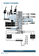
2 2 3 3 4 4 5 5 L MONO 10 R L 11 MONO 12 R L 13 MONO 14 R In (record) IN-TAPE-OUT PHONES CNTRL ROOM OUT OUTPUTS Out (play) L R L R STEREO RETURNS 9 4 In Out Stereo Compressor In Out 5 1 2 AUX SEND Drum Machine Keyboard or other line level input 8 L MONO R In Mono Compressor Out 3 6 CHANNEL INPUTS 7 2 6 6 Stereo Guitar Effects 1 CHANNEL INSERTS 1 ALT 3/4 OUT Direct Boxes 1 MAIN OUT Vocal Mics L R Digital Delay L R Multi Effect Processor 1 2 L R L R MAIN
1 2 2 3 3 4 4 5 5 10 R L 11 MONO 12 R L 13 MONO 14 R In (record) IN-TAPE-OUT PHONES CNTRL ROOM OUT OUTPUTS Out (play) L R L R STEREO RETURNS L MONO 1 2 L R L R AUX SEND 9 5 1 ALT 3/4 OUT MONO 8 R Drum Machine Keyboard or other line level input 4 L R MAIN OUT L In Out Stereo Compressor In Out 3 6 CHANNEL INPUTS 7 2 6 6 Stereo Guitar Effects In Mono Compressor Out 1 CHANNEL INSERTS 1 R Multi Effect Processor 2 Stage Monitors Mono EQ L Mono Power Amplifie
1402-VLZ3 Patchbay Description MIC 1 MIC 2 MIC PRE XDR MIC 4 MIC 3 MIC PRE XDR MIC PRE XDR MIC 5 MIC PRE XDR MIC 6 MIC PRE XDR 2 3 4 RIGHT ALL BAL/UNBAL 1 1 BAL OR UNBAL LINE IN 1 BAL OR UNBAL LINE IN 2 LOW CUT 75 Hz 18dB/OCT U U 0 60 +15dB -45dB U -10dBV C GAIN MI U 0 60 +15dB -45dB GAIN AUX LOW CUT 75 Hz 18dB/OCT -10dBV C GAIN MI U 0 60 +15dB -45dB GAIN AUX U OO OO +15 U OO +15 OO U +15 U OO +15 OO U HI 12kHz +15 U OO +15 OO U HI 12kHz +15 U OO +15
Each LOW CUT switch, often referred to as a High Pass Filter (all depends on how you look at it), cuts bass frequencies below 75 Hz at a rate of 18 dB per octave. We recommend that you use LOW CUT on every microphone application except kick drum, bass guitar, or bassy synth patches. These aside, there isn’t much down there that you want to hear, and filtering it out makes the low stuff you do want much more crisp and tasty.
1402-VLZ3 MIC 1 MIC 2 MIC PRE XDR MIC 4 MIC 3 MIC PRE XDR MIC PRE XDR MIC 5 MIC PRE XDR 7 MIC 6 MIC PRE XDR LEFT/MONO 2 BAL OR UNBAL LINE IN 1 BAL OR UNBAL LINE IN 2 LOW CUT 75 Hz 18dB/OCT LINE IN 3 LOW CUT 75 Hz 18dB/OCT -10dBV C GAIN MI U AUX U OO +15 U OO +15 OO +15 U OO +15 OO LINE IN 5 0 60 +15dB -45dB U +15 U OO +15 OO LOW CUT 75 Hz 18dB/OCT -10dBV C GAIN MI U 0 60 +15dB -45dB GAIN AUX LINE IN 6 -10dBV C GAIN MI U 0 60 +15dB -45dB GAIN AUX U +15 U
14 15 16 12. PHONES 3-4 stereo bus (see MUTE/ALT 3-4 on page 13), Soloed channels, or the Tape input. The volume is adjustable TAPE TAPE with the CONTROL ROOM/SUBMIX [34] fader. 1 1 L INPUT OUTPUT This stereo jack will drive any standard headphone MIC 1 MIC 2 MIC 3 MIC 4 MIC 5 MIC 6 to very loud levels. Walkperson-type phones can also be used with an appropriate adapter. To learn how signals are routed to these outputs, see SOURCE MATRIX [33] on page 16.
1402-VLZ3 21 22 18 19 20 18. POWER CONNECTION 21. POWER SWITCH MIC 1 MIC 2 loseMIC 4 5 6 3 cordMIC Just in caseMICyou the provided with theMIC1402VLZ3, its power jack accepts a standard 3-prong IEC cord like those found on most professional recorders, musical instruments, and computers. MIC PRE XDR MIC PRE XDR MIC PRE XDR BAL OR UNBAL BAL OR UNBAL MIC PRE XDR BAL OR UNBAL MIC PRE XDR BAL OR UNBAL TAPE Press the top of thisTAPErocker switch inwards to turn on 1 L INPUT OUTPUT the mixer.
The ten channel strips look alike, and function identically. The only difference is that the six on the left are for individual mics or mono instruments, and have more gain available, whileMIC the next four are for either stereo MIC 1 MIC 3 MIC 4 2 MIC PRE MIC PRE MIC PRE MIC PRE R R R D D D or mono line-level sources. (Each ofX the stereo channel XDR X X strips is actually two complete circuits. The controls are linked together to preserve stereo.
02-VLZ3 Another way to do the same thing is assign the chanCONSTANT LOUDNESS ! ! ! nels to the ALT 3–4 mix, then patch out of the ALT The 1402-VLZ3’s PAN controls employ a design called ALL BAL/UNBAL LEFT/MONO RIGHT OUTPUT L 1and R backMIC into2an unusedMIC stereo channelMIC 4 TA MIC MIC 5 6 3 IC PR Loudness.” ItXMIC to do with living MIC PRE MIC PRE MIC PRE M R MIC PRE “Constant R MIC Pnothing RE Dhas 1 1 E IN XDR XDR XDR XDR (7–8, 9–10, 11–12, 13–14). If that’s your choice, don’tXD next to a freeway.
This control gives you up to 15 dB boost or cut above 12 kHz, and it is also flat at the detent. Use it to add sizzle to cymbals, and an overall sense of transparency, or edge to keyboards, vocals, guitar and bacon frying. Turn it down a little to reduce sibilance, or to hide tape hiss. Each AUX send level ranges from off through unity (the center detent position) on up to 15 dB of extra gain (when turned fully clockwise).
OR UNBAL 1402-VLZ3 R Output Section LEVEL +4 -10 LINE IN 13-14 33.
35. SOLO MODE (AFL/PFL) Engaging a channel’s SOLO [24] switch will cause this dramatic turn of events: Any existing SOURCE [33] matrix selections will be replaced by the SOLO signal, appearing at the control room outputs, phones outputs, and meter. The audible SOLO levels are then controlled by the CONTROL ROOM / SUBMIX [34] fader. The SOLO levels appearing on the right meter display are not controlled by anything — you wouldn’t want that.
1402-VLZ3 TAPE UTPUT Remember, audio meters are just tools to help assure you that your levels are “in the ballpark.” You don’t have to stare at them (unless you want to). BAL/UNBAL L A WORD ABOUT AUX Sends are outputs, Returns are inputs. The AUX [30] and [31] knobs tap the signal off the channel and sends R it to the AUX SEND [8] outputs.
Owner’s Manual Signals passing through these STEREO RETURN level controls will proceed directly to main mix, with one exception (see next paragraph). The STEREO RETURNs do not have MUTE/ALT 3-4 switches, so if you want these signals to get to the ALT 3-4 mix, you’ll have to patch the effects device’s outputs into one of the stereo channels, and MUTE/ALT [25] those channels. 42. RETURN TO AUX 1 If you want to add reverb or delay to the stage monitor mixes, this is the switch for you.
1402-VLZ3 Appendix A: Service Information Warranty Service Repair If you think your Mackie product has a problem, please check out the following troubleshooting tips and do your best to confirm the problem. Visit the Support section of our website (www.mackie.com/support) where you will find lots of useful information such as FAQs, documentation, and user forums. You may find the answer to the problem without having to send your Mackie product away.
“XLR” Connectors Mackie mixers use 3-pin female “XLR” connectors on all microphone inputs, with pin 1 wired to the grounded (earthed) shield, pin 2 wired to the “high” (”hot” or positive polarity) side of the audio signal and pin 3 wired to the “low” (“cold” or negative polarity) side of the signal. See Figure A. This is all totally aboveboard and in full accord with the hallowed standards dictated by the AES (Audio Engineering Society).
1402-VLZ3 RCA Plugs and Jacks Special Mackie Connections RCA-type plugs (also known as phono plugs) and jacks are often used in home stereo and video equipment and in many other applications (Figure D). They are unbalanced and electrically identical to a 1⁄4" TS phone plug or jack (see Figure C). Connect the signal to the center post and the ground (earth) or shield to the surrounding “basket.” The balanced-to-unbalanced connection has been anticipated in the wiring of Mackie jacks.
Channel Insert jack Direct out with no signal interruption to master. Insert only to first “click.” A mono signal connected to the RIGHT jack will show up in the right bus only. You probably will only want to use this sophisticated effect for special occasions. MONO PLUG Channel Insert jack Direct out with signal interruption to master. Insert all the way in to the second “click.” STEREO PLUG Channel Insert jack For use as an effects loop. (TIP = SEND to effect, RING = RETURN from effect.
1402-VLZ3 Appendix C: Technical Information Specifications Maximum Levels Mic in: +22 dBu Main Mix Noise Tape in: +16 dBu All other inputs: +22 dBu Main Mix XLR out: +28 dBu All other outputs: +22 dBu (20 Hz–20 kHz bandwidth, 1/4" Main out, channels 1–6 Trim @ unity gain, channel EQs flat, all channels assigned to Main Mix, channels 1, 3 and 5 Pan left, 2, 4 and 6 Pan right.
1 3 GAIN MACKIE 1402-VLZ3 SIGNAL FLOW 5/06 STEREO CHANNEL (1 OF 4) LINE IN R LINE IN L MONO CHANNEL (1 OF 6) LINE IN MIC IN 2 PHANTOM POWER (GLOBAL SWITCH) +4 /-10 75Hz HPF MID HI MID HI 3-BAND EQ 80 2K5 12K LO 80 2K5 12K LO LOW CUT INSERT MID HI PRE FADER R IN STEREO RETURN 2 L IN R IN STEREO RETURN 1 L IN (MONO) PRE FADER 3-BAND EQ 80 2K5 12K LO PAN PAN MUTE / ALT POST SOLO POST SOLO LOGIC PFL AFL R AFL L 4 3 2 1 GAIN GAIN RETURN TO AUX 1 AUX SEND
1402-VLZ3 -10dBV C GAIN MI +15 +15 -15 1 MUTE U 5 10 20 30 40 50 60 OO 5 10 20 30 40 50 60 OO dB 10 U SOLO +15 +15 +15 U +15 U U 2 ALT 3 – 4 MUTE L R -15 -15 -15 OO +15 U U SOLO PAN LOW 80Hz MID 2.5kHz HI 12kHz EQ AUX GAIN -10dBV C GAIN MI 0 60 +15dB -45dB OO 5 ALT 3 – 4 PAN LOW 80Hz MID 2.
Please keep your sales receipt in a safe place. This Limited Product Warranty (“Product Warranty”) is provided by LOUD Technologies Inc. (“LOUD”) and is applicable to products purchased in the United States or Canada through a LOUD-authorized reseller or dealer. The Product Warranty will not extend to anyone other than the original purchaser of the product (hereinafter, “Customer,” “you” or “your”). For products purchased outside the U.S. or Canada, please visit www.mackie.
16220 Wood-Red Road NE • Woodinville, WA 98072 • USA United States and Canada: 800.898.3211 Europe, Asia, Central and South America: 425.487.4333 Middle East and Africa: 31.20.654.4000 Fax: 425.487.4337 • www.mackie.com E-mail: sales@mackie.