
Speaker System User Manual

5
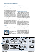
REAR PANEL DESCRIPTION
POWER Switch
Switch up to turn the FUSSION 3000
on, and switch down to turn it off. Make
sure the signal source’s level control is
down before you turn it on.
POWER/PROTECT Indicator
When the
POWER
switch is turned on,
and the linecord is connected to an active
AC Mains supply, this indicator lights green
to let you know that you’re ready to rock
and roll. If one of the protection circuits in
the FUSSION 3000 should trigger, this indi-
cator changes to red. The protection circuits
include RMS limiting on the input and
thermal protection on the heatsink. If the
output begins to clip for more than a few
seconds, the
POWER/PROTECT
indicator
changes to red and the RMS limiting pro-
tection circuit discretely reduces the input
signal until the output is just below clip-
ping. If this should happen, turn down the
level at the source (mixing console) until
the
PROTECT
light changes back to green.
If the thermal protection circuit should
get activated, the
POWER/PROTECT
indicator
changes to red and the amplifiers shut down
until the heatsinks cool to a safe operating
level. Once the amplifier cools, the thermal
protection circuit resets and normal opera-
tion resumes. You should determine what is
causing the overheating condition and take
steps to remedy it (i.e., direct sunlight on
the heatsink, not enough clearance for air
to circulate freely around the heatsink, etc.).
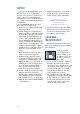
AC Receptacle
This is where you connect the AC
linecord to provide AC power to the
FUSSION 3000’s built-in power amplifiers.
Plug the linecord into an AC socket prop-
erly configured for your particular model.
The FUSSION 3000 is shipped with a
connector that mates with the AC recep-
tacle on the rear panel. Use heavy gauge
wire for the linecord to avoid power losses
across the wire. (See page 8 for more info.)
The bar
A
on the rear panel is there to
secure the linecord and prevent it from acci-
dentally getting pulled loose from the AC
receptacle. Wrap the linecord through the
bar and tie it in a knot to secure it.
Note: You can change the AC voltage
configuration from 115V to 230V internally
by reconfiguring the transformer primary
wiring on the power supply board. Contact
Mackie Technical Support for instructions
(1-800-258-6883).
FUSE
Always replace the fuse with the type in-
dicated on the rear panel. Never replace the
fuse with one of a higher value than indi-
cated on the rear panel.
WARNING: Make sure
you use the correct fuse
relative to the AC operat-
ing voltage.
115VAC=16A Slow-Blow
230VAC=10A Slow-Blow
FUSE
3000
FUSSION
WARNING:
THIS SURFACE MAY REACH HIGH TEMPERATURE DURING
STANDARD USE. TO ENSURE PROPER OPERATION ALLOW A MINIMUM OF 6 INS.
OF CLEARANCE FROM THIS SURFACE AND ADEQUATE VENTILATION. TO REDUCE
THE RISK OF ELECTRIC SHOCK DO NOT REMOVE THIS PANEL OR ANY ATTACHED
COMPONENT. NO OPERATOR SERVICEABLE PARTS INSIDE. REFER SERVICING TO
QUALIFIED PERSONNEL. TO REDUCE THE RISK OF FIRE OR ELECTRIC SHOCK, DO NOT
EXPOSE THIS APPLIANCE TO RAIN OR MOISTURE.
RISK OF ELECTRIC SHOCK
DO NOT OPEN
REPLACE WITH THE SAME TYPE FUSE AND RATING.
DISCONNECT SUPPLY CORD BEFORE CHANGING FUSE
UTILISE UN FUSIBLE DE RECHANGE DE MÊME TYPE.
DEBRANCHER AVANT DE REMPLACER LE FUSIBLE
CAUTION
AVIS:
RISQUE DE CHOC ELECTRIQUE — NE PAS OUVRIR
SERIAL NUMBER
MANUFACTURING DATE
FS
CONCEIVED, DESIGNED, AND MANUFACTURED BY MACKIE DESIGNS INC, WOODINVILLE, WA, USA
AND MACKIE EUROPE • MANUFACTURED IN ITALY • COPYRIGHT ©1998 •
THE FOLLOWING ARE TRADEMARKS OR REGISTERED TRADEMARKS OF MACKIE DESIGNS INC.:
"MACKIE", AND THE "RUNNING MAN" FIGURE • PATENT PENDING
™
10
0
MAIN INPUTLOOP OUT
PIN 1- GND / PIN 2- POS (+) /
PIN 3- NEG (-)
HIGH PASS
85Hz - 20kHz
FULL RANGE
55Hz - 20kHz
POWER (GREEN)
PROTECT (RED)
FILL OUT
85Hz - 20kHz
OUTPUT
LEVEL
SUB-OUT
20Hz - 85Hz
PHASE
0˚ 180˚
MAIN INPUT
ON
FUSE
16A / SB
NEMA LS-20 20A-115VAC
PARALLEL
115VAC Version
FUSE
ON
FUSE
10A / SB
10A - 230 VAC
230VAC Version
A