
Service manual

9
DSP SYSTEM
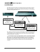
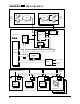
A simplified block diagram of the DSP system is shown on the next page. At the heart of
the system is an Analog Devices ADSP-2181. It acts as the console CPU, and controls all
functions and communications within the DSP system. There are 24 proprietary DSP chips
to handle the actual audio processing. Parallel processing with the 24 DSPs allows the
d8b to complete all processing within one sample.
Operating instructions are loaded from the Remote CPU as the system boots. The
EPROM does not contain operating firmware. Think of the EPROM as BIOS, it provides the
system with basic instructions to make sure it powers up correctly and sets up to receive
the operating software from the Remote CPU.
CLOCKS
All audio clocks for the DSP system originate at the clock (sync) card. The master clock is
512 x sample rate. See page 24 for some more details.
CODEC BOARD
The CODEC board contains 24 channels of A/D and D/A. Each ADC converts two
analog audio signals into a two channel serial format which is sent to the DSP chips. All
digital audio signals within the d8b are in this two channel format. The DACs convert this
stream back to 2 channels of lovely analog audio.
DSP BOARD
Each of the 24 DSP chips has two serial inputs, DR_0 and DR_1, and two serial outputs,
DT_0 and DT_1, a total of 48 inputs and 48 outputs (remember that each serial input is 2
channels of audio, so that’s 96 channels!, but they’re not all used). Digital audio data
comes from and is sent to the CODEC board, I/O cards, and FX cards.
Y2 is the processor clock from which is derived CLK_1, CLK_2, CLK_3, CLK_4 and CLKIN.
Y1 is a UART clock.
DSP INPUTS DSP OUTPUTS
12 Mic/Line Inputs 8 Subgroups
12 Line Inputs 2 L/R Mix
24 Tape Input Cards 24 Tape Returns Cards
16 FX Card Returns 16 FX Card Sends
2 Meter (monitor) 12 Aux sends
8 Alt Input Card 8 Alt Output Card
2 Solo
The processing algorithm works in such a way that each serial output consists of one
mix and one direct output. In order to route mixes to the same DACs the serial data is
juxtaposed in sync with the L/R clock.
There are three status indicators on the board: D2 (green),D3 (yellow), D1 (red).
•If all three are on, a fault has been detected.
•If the red LED is on solidly, then this is operating OK.