
User's Manual

D8B Manual • Chapter 2 • page 22
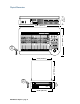
It’s Time to Locate Everything…
No matter how fast you want—or need—to get
started, take advantage of this simple map of the
territory: it provides the Fast Track overview of
the D8B. It’s amazing how artistically supportive
this console is. It’s well worth your time to take a
look at all the controls so you can put them to
work efficiently.
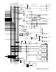
Rear Panel Description
This section describes rear panel connector types,
their functions, and associated signal buses.
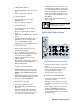
Channels 1–12 Inputs
+48V
PH
LINE IN
INSERT
+48V
PH
LINE IN
INSERT
+48V
PH
LINE IN
INSERT
+48V
PH
LINE IN
INSERT
+48V
PH
LINE IN
INSERT
+48V
PH
LINE IN
INSERT
6
MIC
5
MIC
4
MIC
3
MIC
2
MIC
1
MIC
Each channel contains:
• XLR mic input. Be sure the MIC button is pressed
down on the control surface channel strip.
• Phantom power On/Off button depending on
mic requirements.
• 1/4" TRS line input—balanced or unbalanced.
Be sure the MIC switch is in the up position
on the control surface channel strip.
• 1/4" TRS channel insert/direct output jack.
Channels 13–24 Inputs
19
13
20
14
21
15
22
16
23
17
24
18
LINE INPUTS
(BAL /UNBAL)
Channels 13 through 24 have 1/4" TRS (Tip/Ring/
Sleeve) line input connectors that accept balanced
and unbalanced signals.
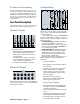
Card Cage Section
DIGITAL I/O SYNC ALT I/O TAPE IN/OUTS
A B C D
DIGITAL EFFECTS CARDS
OPT•8
PDI•8
AES/EBU I/O
OUT
IN
IN
OUT
DIGITAL I/O
1
AES/EBU
DIGITAL I/O
2
S/PDIF
WORD
CLOCK
OUT
APOGEE
CLOCK I/O
WORD
CLOCK
IN
SYNC
IN OUT
TDIF
ADAT OPTICAL
ANALOG IN ANALOG OUT
ANALOG I/O
This is where you plug in the optional I/O cards of
your choosing, to customize the Digital 8•Bus for
your own application.
There are three slots assigned as TAPE IN/OUTS.
Each slot provides I/O for 8 channels, so you can
add up to 24 tape sends and returns, or additional
inputs and outputs.
• TO TAPE (OUTPUT) – The D8B can route any
channel in Fader Banks 1, 2 and 3 to the
multitrack through these connectors. In addition,
the bus outputs in Fader Bank 4 (MASTERS) can
be routed out the tape outputs.
• FROM TAPE (INPUT) – Multitrack outputs are
fed back into channels 25–48 (Fader Bank 2)
through these connectors. Depending on the
specific I/O card, these inputs will receive any
line-level analog or digital signal.
Each I/O card contains its own labeling protocol,
but the fundamental concepts described above
pertain to all.
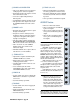
1 Analog I/O (AIO•8)
• Each 25-pin D-sub connector handles 8 balanced
analog channels.
• Top connectors send line-level outputs to the
multitrack (or other line-level equipment).
• Bottom connectors receive line-level analog
signal from the multitrack outputs (or other
line-level equipment).
• Each card offers I/O for 8 channels.
• Connectors are compatible with TASCAM
DA-88, 25-pin analog connectors.
2 Apogee Digital I/O (DIO•8)
• Two digital-format ins and outs: ADAT optical
(fiber optic connections) and TASCAM TDIF
(25-pin D-sub connections).
• Select one digital format at a time in the Setup
screen.
• One BNC sync connector for master clock connec-
tion from the D8B to TASCAM clock recipient.
• Use the DIO•8 card as a format converter be-
tween either optical and/or TDIF.
1
4
6
7
8
5
2
3