
User Manual


DL32R Owner’s Manual
5
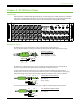
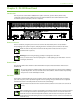
Chapter 2 : DL32R Front Panel
Introduction
Each DL32R mixer is outtted with 24 XLR input jacks, 8 combo input jacks, 14 XLR output jacks, an XLR AES
output jack, 1/4" L/R monitor output jacks, one 1/4" phones output jack (and corresponding phones knob)
and power and network LEDs. Let’s take a look at each of these features, starting with the inputs.
XLR and 1/4" Inputs
All channels may accept a balanced mic or line-level signal using an XLR connector.
They are wired as follows, according to standards specied by the AES (Audio Engineering Society).
XLR Balanced Wiring:
Pin 1 = Shield (ground)
Pin 2 = Positive (+ or hot)
Pin 3 = Negative (– or cold)
In addition to accepting balanced mic or line-level signals using an XLR connector, channels 25-32
may also accept 1/4" line-level signals driven by balanced or unbalanced sources.
To connect balanced lines to these inputs, use a 1/4" Tip-Ring-Sleeve (TRS) plug. “TRS” stands for
Tip-Ring-Sleeve, the three connection points available on a stereo 1/4" or balanced phone jack or plug.
TRS jacks and plugs are used for balanced signals and stereo headphones and are wired as follows:
1/4" TRS Balanced Mono Wiring:
Sleeve = Shield
Tip = Hot (+)
Ring = Cold (–)
To connect unbalanced lines to these inputs, use a 1/4" mono (TS) phone plug, wired as follows:
1/4" TS Unbalanced Mono Wiring:
Sleeve = Shield
Tip = Hot (+)
2
3
1
SHIELD
COLD
HOT
SHIELD
COLD
HOT
3
2
1
SLEEVE
TIPSLEEVE
TIP
RING
RING
TIP
SLEEVERING
SLEEVE
TIP
TIPSLEEVE
TIP
SLEEVE