
Music Mixer User Manual

MORE INFORMATION
THESE SPECIFICATIONS
ARE AVAILABLE ON 3.5"
PC & MAC FORMAT DISK IN
POPULAR WORD
PROCESSOR FORMATS
■
CALL 800/258-6883
FAX 425/487-4337
OUTSIDE THE U.S., CALL
425/487-4333
2/6/98
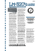
1. GENERAL CONFIGURA-
TION. The audio mixer shall
have a rack-mountable
frame which accommodates
16 stereo input channels, 2
main output channels and 2
alternate output channels.
Each input channel shall be
capable of accepting either
stereo or monaural signals,
and shall be fitted with
stereo level, equalization,
balance, solo, muting and
auxiliary send controls,
level-indicating (-20) LEDs
and overload (O/L) LEDs.
Input channels 1 through 4
shall each be fitted with left
and right insert jacks. The
main output channels shall
each have a level control, an
electronic level meter and a
bus insert jack.
Additionally, the mixer shall
include a solo function, a
monitor switching and
control function, 4 stereo
effects return inputs with
alternate routing switching,
2 stereo pairs effects send
outputs, 2 monaural effects
send outputs, 1 stereo pair
control room output, 1
stereo headphone output,
1 set of stereo tape re-
corder RCA outputs, and 1
set of stereo tape monitor
RCA inputs. The mixer shall
also include 2 independent
patchable microphone pre-
amplifiers, each fitted with
an electronically balanced
XLR input switchable phan-
tom microphone powering, a
preamplifier gain control and
a balanced line-level output.
2. POWER SUPPLY. All
necessary operating volt-
ages for the mixer shall be
provided by an internal
shielded power supply.
3. INPUT CHANNEL CON-
NECTIONS. Each mixer
input channel shall have a
left and a right electroni-
cally balanced line-level
input, accommodating a
nominal line level of be-
tween –10 dBV and +4
dBu, and appearing on the
rear panel as
1
⁄4" TRS
phone jacks (tip hot, ring
cold). The jacks shall be fit-
ted with internal switches
to accommodate monaural
configuration. Additionally,
input channels 1 through 4
shall offer left and right
unbalanced insert connec-
tions, appearing on the rear
panel as
1
⁄4" TRS phone
jacks (tip send, ring return).
4. INPUT CHANNEL LEVEL
AND ASSIGNMENT CON-
TROLS AND INDICATORS.
Each mixer input channel
shall be equipped with a
rotary dual gain control, a
solo switch, a mute switch
which also functions as an
assignment switch to the
alternate output channels,
and a stereo balance control.
5. INPUT CHANNEL
EQUALIZATION. Each mixer
input channel shall be
equipped with a stereo
equalization function. The
equalizer shall have three
sections: a low-frequency
shelving equalizer with the
knee set at 80 Hz and a
range of ±15 dB; a mid-
frequency peaking equalizer
centered at 2.5 kHz featur-
ing a bandwidth of 2 oc-
taves and a range of ±12
dB; and a high-frequency
shelving equalizer with the
knee set at 12 kHz and a
range of ±15 dB.
6. INPUT CHANNEL AUXIL-
IARY SENDS. Each mixer
input channel shall have 1
stereo auxiliary send control
and 1 monaural auxiliary
send control. The auxiliary
send controls shall be
switchable between 2 sets
of auxiliary send buses,
32x2x2 STEREO LINE MIXER
®