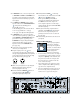
20 VAC 60 Hz 2000 WATTS SENSITIVITY 11 17 19 21 23 3v 31 29 27 2v SIG SIG 17 –9 –20 –9 –20 31 29 27 2v CH 2 TO REDUCE THE RISK OF FIRE OR ELECTRIC SHOCK, DO NOT EXPOSE THIS EQUIPMENT TO RAIN OR MOISTURE. DO NOT REMOVE COVER. NO USER SERVICEABLE PARTS INSIDE. REFER SERVICING TO QUALIFIED PERSONNEL. 1.
CAUTION AVIS RISK OF ELECTRIC SHOCK DO NOT OPEN RISQUE DE CHOC ELECTRIQUE NE PAS OUVRIR CAUTION: TO REDUCE THE RISK OF ELECTRIC SHOCK DO NOT REMOVE COVER (OR BACK) NO USER-SERVICEABLE PARTS INSIDE REFER SERVICING TO QUALIFIED PERSONNEL ATTENTION: POUR EVITER LES RISQUES DE CHOC ELECTRIQUE, NE PAS ENLEVER LE COUVERCLE. AUCUN ENTRETIEN DE PIECES INTERIEURES PAR L'USAGER. CONFIER L'ENTRETIEN AU PERSONNEL QUALIFIE.
Lend Me Your Ears Exposure to extremely high noise levels may cause permanent hearing loss. Individuals vary considerably in susceptibility to noiseinduced hearing loss, but nearly everyone will lose some hearing if exposed to sufficiently intense noise for a period of Duration in Sound level dBA time. The U.S. Government’s Occu- hours per day (slow response) 8 90 pational Safety and 6 92 Health Administra4 95 tion (OSHA) has 3 97 2 100 specified the per1.
READ THIS PAGE! QUICK START I got ants in my pants and I got to dance! INSTALLATION The M•2600 amplifier must only be installed in a rack. See page 29 for special details regarding rack mounting and thermal considerations. DO NOT BLOCK THE VENTILATION PORTS The M•2600 draws its ventilation air in from the front and out through the side panels. It needs plenty of fresh air to stay cool. CONNECTIONS AND SETTINGS 1.
7. In BRIDGED mode, connect an input cable to CHANNEL 1’s INPUT or CHANNEL 2. If you want to use both inputs, the two input signals are summed internally to produce a mono signal. 8. In STEREO and MONO modes, connect speaker cables to the SPEAKER OUTPUTS , using either the binding post or Speakon® connectors. • The binding post connectors are wired red = hot (+) and black = cold (–). • See page 35 for Speakon wiring details. 9.
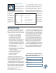
HOW TO USE THIS MANUAL APPLICATION DIAGRAMS A PLUG FOR THE CONNECTORS SECTION Mackie’s chain gang of illustrators have created easy-to-understand diagrams of popular studio and live-sound setups. Your setup will probably be different in some way, but these diagrams will help you see the big picture so you can add your own finishing touches. Also at the back of this manual is a section on connectors: XLR, TRS, binding post connectors, balanced connectors, unbalanced connectors, and Speakon® connectors.
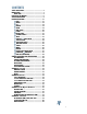
CONTENTS SAFETY INSTRUCTIONS .................................................. 2 INTRODUCTION ............................................................ 3 QUICK START ......................................................... 4 HOW TO USE THIS MANUAL .......................................... 6 APPLICATION DIAGRAMS .............................................. 8 FEATURE DESCRIPTIONS .............................................. 17 GAIN .............................................................
APPLICATION DIAGRAMS The following pages show some of the more common uses for the M•2600, including stereo, mono, and bridged operation. USING THE LOW CUT FILTER AMP MODE LOW CUT FILTER CROSSOVER TYPICAL 35 Hz SUB WOOFE The application diagrams include some small graphs of the frequency range going into and coming out of the amplifier. These graphs show the effect of the LOW CUT FILTER to roll off the lower frequencies going to the speakers.
TWO M•2600S: MAIN SPEAKERS AND STAGE MONITORS 9 120 VAC 60 Hz 2000 WATTS 120 VAC 60 Hz 2000 WATTS (play above 35Hz in this example). MAIN SPEAKERS CAUTION WARNING: TO REDUCE THE RISK OF FIRE OR ELECTRIC SHOCK, DO NOT EXPOSE THIS EQUIPMENT TO RAIN OR MOISTURE. DO NOT REMOVE COVER. NO USER SERVICEABLE PARTS INSIDE. REFER SERVICING TO QUALIFIED PERSONNEL. AVIS: RISQUE DE CHOC ELECTRIQUE — NE PAS OUVRIR SERIAL NUMBER MANUFACTURING DATE – – LETHAL VOLTAGES MAY APPEAR AT OUTPUT TERMINALS.
M•2600: MAIN SPEAKERS AND STAGE MONITORS WITH ONE AMPLIFIER WARNING: 120 VAC 60 Hz 2000 WATTS TO REDUCE THE RISK OF FIRE OR ELECTRIC SHOCK, DO NOT EXPOSE THIS EQUIPMENT TO RAIN OR MOISTURE. DO NOT REMOVE COVER. NO USER SERVICEABLE PARTS INSIDE. REFER SERVICING TO QUALIFIED PERSONNEL.
M•2600: EIGHT MONITOR SPEAKERS-MONO MODE 11 120 VAC 60 Hz 2000 WATTS The TOTAL IMPEDANCE must be greater than 2 ohms per channel. In this example, each speaker must be 8 ohms or greater. CAUTION EXPOSE THIS EQUIPMENT TO RAIN OR MOISTURE. DO NOT REMOVE COVER. NO USER SERVICEABLE PARTS INSIDE. REFER SERVICING TO QUALIFIED PERSONNEL.
M•2600: STEREO SYSTEM WITH TWO AMPLIFIERS IN BRIDGED MODE CH PIN 1+ CH1+ PIN 1– CH1– PIN 2+ & 2 – NOT USED 1 – – CH CAUTION WARNING: AVIS: RISQUE DE CHOC ELECTRIQUE — NE PAS OUVRIR TO REDUCE THE RISK OF FIRE OR ELECTRIC SHOCK, DO NOT EXPOSE THIS EQUIPMENT TO RAIN OR MOISTURE. DO NOT REMOVE COVER. NO USER SERVICEABLE PARTS INSIDE. REFER SERVICING TO QUALIFIED PERSONNEL. LETHAL VOLTAGES MAY APPEAR AT OUTPUT TERMINALS.
USING THE CROSSOVER AMP MODE LOW CUT FILTER CROSSOVER TYPICAL 35 Hz SUB WOOFE The following three pages show how the internal crossover can be used to biamp your system. One amplifer plays the lower frequencies, while another plays the highs. The electronic crossover inside the M•2600 splits the frequency band into two ranges, one below the crossover point (LOW OUT) and one above (HIGH OUT). The LOW OUT is available to the amplifier section for powering subwoofers.
M•2600: STEREO SYSTEM BIAMPED WITH SUBWOOFERS, OPTION 1 SUBWOOFERS 120 VAC 60 Hz 2000 WATTS (play above 90Hz in this example) MAIN SPEAKERS 120 VAC 60 Hz 2000 WATTS (play between 20Hz and 90Hz in this example) CAUTION WARNING: TO REDUCE THE RISK OF FIRE OR ELECTRIC SHOCK, DO NOT EXPOSE THIS EQUIPMENT TO RAIN OR MOISTURE. DO NOT REMOVE COVER. NO USER SERVICEABLE PARTS INSIDE. REFER SERVICING TO QUALIFIED PERSONNEL.
M•2600: STEREO SYSTEM BIAMPED WITH SUBWOOFERS, OPTION 2 15 120 VAC 60 Hz 2000 WATTS (play between 20Hz and 90Hz in this example) SUBWOOFERS 120 VAC 60 Hz 2000 WATTS (play above 35Hz in this example) MAIN SPEAKERS CAUTION WARNING: TO REDUCE THE RISK OF FIRE OR ELECTRIC SHOCK, DO NOT EXPOSE THIS EQUIPMENT TO RAIN OR MOISTURE. DO NOT REMOVE COVER. NO USER SERVICEABLE PARTS INSIDE. REFER SERVICING TO QUALIFIED PERSONNEL.
M•2600: STEREO SYSTEM BIAMPED WITH BRIDGED SUBWOOFER 120 VAC 60 Hz 2000 WATTS (play above 90Hz in this example) MAIN SPEAKERS 120 VAC 60 Hz 2000 WATTS AVIS: RISQUE DE CHOC ELECTRIQUE — NE PAS OUVRIR WARNING: – TO REDUCE THE RISK OF FIRE OR ELECTRIC SHOCK, DO NOT EXPOSE THIS EQUIPMENT TO RAIN OR MOISTURE. DO NOT REMOVE COVER. NO USER SERVICEABLE PARTS INSIDE. REFER SERVICING TO QUALIFIED PERSONNEL.
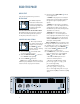
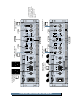
FEATURE DESCRIPTIONS GAIN/dB 3v 21 23 25 2v 19 27 17 29 31 GAIN 0 0 11 SENSITIVITY 33 1v 1.23v (+4dBu) These front panel knobs allow you to control the levels going into the output section of the M•2600 amplifier. Their travel is detented, meaning there are 20 built-in “resting points” so you can easily set both controls to the same level. Usually, these controls are set to maximum. The gain structure of the amplifier is designed so that a +4 dBu (1.
You may wonder why we didn’t use just one stereo control to control both sides. That’s in case your application requires a left/right imbalance (due to an irregularly shaped room) or if you’re using the two sides for completely different purposes (monitor in channel 1 and side-fill in channel 2, for instance). Besides, they look cool. So what are the pros and cons of these two approaches? The reason some amplifier manufacturers use the constant gain approach is because the noise specification looks better.
SIG SIG (short for “signal present”) is the lowest step in the meter ladder. It senses the signal prior to the GAIN control, so when SIG is lit, you know the M•2600 is receiving signal. If it’s the only meter LED lit (meaning the other meter LEDs are not lit), the M•2600 is receiving a very weak signal (below –20 dB). PROTECT If the PROTECT LEDs are on, the M•2600’s output section has shut down. That, of course, means you won’t hear anything until you rectify the situation.
Note: When using the amplifier in BRIDGED mode, both SHORT LEDs will light under shorted or low impedance conditions. This is an indication of a problem that requires further investigation. Please see “Do The Math: Ohms, Loads and Such” in Appendix D to learn about speaker loads. As the internal temperature of the amplifier rises, the fan speed gradually increases. More air moves through the constant temperature gradient cooling tunnel to remove additional heat from the output transistors.
What’s that? Why doesn’t the fan just go fast all the time? Well, if it did, you might actually hear it whirring during your quiet moments (there are quiet moments in your life, aren’t there?). While this whirring would be of no concern in most live-sound situations, it could become annoying in a control room environment.
SPEAKER OUTPUTS In addition to binding posts, the M•2600 also has Speakon® SPEAKER OUTPUTS, so you can use speaker cables with Speakon connectors. These locking connectors are easy to attach and are capable of handling high currents and low impedance loads. Pin 1+ is positive (+) and pin 1– is negative (–). They’re wired in parallel with the binding posts and behave exactly the same (there is a separate Speakon mode).
Ordinarily, applying a positive voltage to a speaker’s positive input and negative voltage to the negative input results in an outward excursion of the woofer. But some woofers are built with reverse polarity, meaning that the above conditions result in an inward excursion. If you’re not sure which type of speakers you have, take a look at their literature. If you’re still not sure, here is a simple test: remove the speaker wires from the back of the speakers, then take a 1.
You can connect an unbalanced XLR cable to the M•2600, although this would be unusual — as unusual as an unbalanced XLR output. However, if you have an unbalanced XLR connection to make, refer to the “Connectors” section (Appendix B) at the back of this manual for more information.
CROSSOVER SWITCH Level, dB 5dB This three-way switch allows you to set the crossover point of the internal CROSSOVER to either 60Hz, 90Hz or 120Hz. This affects two things: • The THRU output , if the THRU switch is set to LOW OUT or HIGH OUT. • The SPEAKER OUTPUTS , if the OUTPUT APPLICATION switch is set to LOW OUT. The amplifier then plays the frequency range below the crossover point. affects Note: The LOW CUT FILTER and the SPEAKER both the THRU outputs in the cases above.
STEREO mode (separate left and right inputs, separate left and right outputs) is the typical setup for amplifying stereo signals. MONO mode (sometimes called DualMono — one or two inputs, two mono outputs) is for sending a mono signal to two different speaker sets, with separately-adjustable GAIN controls. BRIDGED mode (sometimes called Bridged-Mono — one or two inputs, one mono output) uses both sides of the amp to send great power to one speaker.
OUTPUT APPLICATION SWITCH The LIMITER works independently on each channel. It senses when the amplifier channel is about to be overdriven and attenuates the overall level just enough to keep the signal from clipping. Clipping occurs when the output voltage no longer linearly follows the input voltage and simply stops. This causes a sine wave to “square off,” and the average power going into the speaker is roughly double that of a sine wave.
LOW OUT (SUBWOOFER) Here’s a special surprise: If you bought the M•2600 amplifier to power a subwoofer system, you just saved yourself the cost of a crossover! The M•2600 amp has an active crossover built in. The amplifier can play the frequencies below the crossover point set with the CROSSOVER switch . 5dB 0dB –5dB –10dB –15dB 20Hz 100Hz 1kHz 10kHz 20kHz Crossover settings. Here’s how to configure it: 1. Turn the M•2600’s POWER off. 2. Set the OUTPUT APPLICATION switch to LOW OUT (SUBWOOFER). 3.
GENERAL PRECAUTIONS AND CONSIDERATIONS RACK MOUNTING and THERMAL CONSIDERATIONS The M•2600 is a high-power amplifier, and special consideration to ventilation cannot be ignored: • The amplifier must only be installed in a rack. It requires three rack space units (3 U = 5.2"). It also requires 16.7" depth inside the rack, including the rear supports. • There must be a minimum of 1 empty rack space (1-3/4”, 35mm) above and below.
It is recommended that a stiff supply of AC power be used because the amplifier places high current demands on the AC line. The more power that is available on the line, the louder the amplifier will play and the more peak output power will be available for cleaner, punchier bass. A suspected problem of “poor bass performance” is often caused by a weak AC supply to the amplifier. The M•2600 has an in-rush limiting circuit and relay that will prevent popping the house circuit breakers during turn-on.
70V DISTRIBUTION SYSTEMS A distributed sound system uses a constantvoltage, high-impedance network that feeds a number of tapped transformers which, in turn, deliver power to individual speakers. Each tap is rated in watts, so you can select the amount of power delivered to the speaker. Developed for distributed paging and public address systems, one benefit of such a system is that it eliminates complicated impedance calculations when setting up a multi-speaker system.
APPENDIX A: Service Info WARRANTY SERVICE If you think your amplifier has a problem, please do everything you can to confirm it before calling for service, including reading through the following Troubleshooting section. Doing so might save you from being deprived of your Mackie amplifier. Of all Mackie products returned for service (which is hardly any at all), many are coded “CND” — Could Not Duplicate, which usually means the problem lay somewhere else in the system.
As soon as the music gets loud, the amp shuts down! • Check the M•2600’s meters. Be sure that OL is not lighting up frequently or continuously. • Can the amp breathe? The M•2600 amps draw their ventilation air in from the front and out through the side panels. They need plenty of fresh air to stay cool. Do not block the ventilation ports. • Is the SHORT LED lit? If so, you’ve got a dead short somewhere in your speaker setup, or the total impedance of the load is too low.
APPENDIX B: Connectors “XLR” CONNECTORS Mackie amplifiers use 3-pin female “XLR” connectors on each input, with pin 1 wired to the grounded (earthed) shield, pin 2 wired to the “high” (“hot” or positive polarity) side of the audio signal, and pin 3 wired to the “low” 2 SHIELD HOT COLD SHIELD 1 3 (output from mixer), ring to signal return (input back into mixer), and sleeve to ground (earth). • Balanced mono circuits.
• When connecting an unbalanced output to a balanced input, be sure that the signal high (hot) connections are wired to each other. The unbalanced ground (earth) connection should be wired to the low and the ground connections of the balanced input. If there are ground-loop problems, try connecting the unbalanced ground connection only to the input low connection, and leaving the input ground connection disconnected. • In some cases, you will have to make up special adapters to interconnect your equipment.
APPENDIX C: Arcane Mysteries Illuminated BALANCED LINES Balanced lines offer increased immunity to external noise (specifically, hum and buzz). Because a balanced system is able to minimize noise, it is the preferred interconnect method, especially in cases where very long lengths of cable are being used.
10. Walk outside — look at the horizon. See any radio towers? Locate potential sources of RF interference and plan for them before you begin construction. Know the frequency, transmitter power, etc. You can get this information by calling the station. Remember that many broadcast stations change the antenna coverage pattern and transmitter power at night. 11. Don’t use hardware-store light dimmers. 12. Don’t allow for anything other than microphone inputs at stage/altar locations.
BI-AMPLIFIED AND TRI-AMPLIFIED SYSTEMS Biamplified and triamplified systems use separate power amplifiers to power each individual low-frequency and high-frequency driver. An electronic crossover (a.k.a. active crossover) is located between the signal source and the power amplifier. The advantages of this method include: • Increased headroom available from each amplifier, since they’re amplifying only a portion of the entire audio spectrum.
APPENDIX D: Technical Info DO THE MATH: OHMS, LOADS, AND SUCH Remember: As the load gets “heavier,” its value in ohms goes down. For instance, a 2-ohm speaker load is twice as “heavy” as a 4-ohm load. An ohm is a unit of resistance — the more ohms, the more resistance (impedance). The more the resistance, the less the power. It can all seem backwards at first. Just remember that a dead short means no resistance at all, or zero ohms.
SPECIFICATIONS M•2600 Maximum Power at 1% THD, midband: 500 watts per channel into 8Ω 850watts per channel into 4Ω 1300 watts per channel into 2Ω 1700 watts into 8Ω bridged 2600 watts into 4Ω bridged Continuous Sine Wave Average Output Power, both channels driven: 425 watts per channel into 8Ω from 20Hz to 20kHz, with no more than 0.025% THD 700 watts per channel into 4Ω from 20Hz to 20kHz, with no more than 0.05% THD 1000 watts per channel into 2Ω from 20Hz to 20kHz, with no more than 0.
Power Consumption Country AC input requirements Line Range Power Consumption (1/8 of 2Ω resistive power/ nominal) North America 120 V, 60 Hz 76 V - 132 V 1650 W, 18.2 A 240 V, 60 Hz 152 V - 264 V 1650 W, 9.1 A Europe 240 V, 50/60 Hz 152 V - 264 V 1650 W, 9.1 A Korea 240 V, 60 Hz 152 V - 264 V 1650 W, 9.1 A 100 V, 50/60 Hz 63 V - 110 V 1000 W, 13.8 A (4Ω) Japan * 200 V, 50/60 Hz 126 V - 220 V 1650 W, 10.9 A The 100 V version of the Japanese model is not rated into 2Ω.
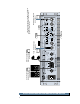
MACKIE DESIGNS M•2600 BLOCK DIAGRAM 9/21/1998 THRU OUTPUT (XLR-MALE) LINE INPUT (XLR-FEMALE) LINE INPUT (1/4" TRS) THRU OUTPUT (XLR-MALE) LINE INPUT (XLR-FEMALE) LINE INPUT (1/4" TRS) FUSE LOW CUT FILTER FREQ LOW CUT FILTER FREQ CROSSOVER LAMP POWER SWITCH TRANSFORMER THERMAL IN-RUSH LIMIT CROSSOVER HIGH LOW 60-90-120Hz THRU–LOW–HIGH CH 2 SIG HIGH LOW 60-90-120Hz THRU–LOW–HIGH CH 1 SIG CH–2 TOROIDAL POWER TRANSFORMER IN-RUSH CONTROL LIMIT–OFF-LOW OUT Σ STEREO-MONO-BRIDGE
NOTES 43
Some of the people at our factory who helped design, build, sell, and support your product. ® ® ™ ® Mackie Designs Inc. 16220 Wood-Red Rd. NE • Woodinville, WA 98072 • USA US & Canada: 800/898-3211 Europe, Asia, Central & South America: 425/487-4333 Middle East & Africa: 31-20-654-4000 Fax: 425/487-4337 • www.mackie.com E-mail: sales@mackie.