MICROSERIES1202-VLZ MIC/LINE MIXER OWNER’S MANUAL ON TM ON CAUTION UTILISE UN FUSIBLE DE RECHANGE DE MÊME TYPE. DEBRANCHER AVANT DE REMPLACER LE FUSIBLE ALT OUTPUT CONTROL ROOM LEFT RIGHT PHANTOM R +4 MIC 120 VAC 50/60 Hz 20W 315mA/250V SLO-BLO MANUFACTURING DATE SERIAL NUMBER AVIS: RISCQUE DE CHOC ÉLECTRIQUE — NE PAS OUVRIR REPLACE WITH THE SAME TYPE FUSE AND RATING.
CAUTION AVIS RISK OF ELECTRIC SHOCK DO NOT OPEN RISQUE DE CHOC ELECTRIQUE NE PAS OUVRIR CAUTION: TO REDUCE THE RISK OF ELECTRIC SHOCK DO NOT REMOVE COVER (OR BACK) NO USER-SERVICEABLE PARTS INSIDE REFER SERVICING TO QUALIFIED PERSONNEL ATTENTION: POUR EVITER LES RISQUES DE CHOC ELECTRIQUE, NE PAS ENLEVER LE COUVERCLE. AUCUN ENTRETIEN DE PIECES INTERIEURES PAR L'USAGER. CONFIER L'ENTRETIEN AU PERSONNEL QUALIFIE.
READ THIS PAGE!!! We realize that you must be dying to try out your new MicroSeries 1202-VLZ. Or you might be one of those people who never read manuals. Either way, all we ask is that you read this page NOW, and the rest can wait until you’re good and ready. But do read it — you’ll be glad you did. LEVEL-SETTING PROCEDURE Message to seasoned pros: do not set levels using the old “Turn the trim up until the clip light comes on, then back off a hair” trick.
INTRODUCTION Thank you! There are a lot of makes and models of compact mixers out there, all competing for your bucks… but you have voted with your wallet for the folks in Woodinville who specialize in American-made mixers. Now that you have your MicroSeries 1202-VLZ, find out how to get the most from it. That’s where this manual comes in.
CONTENTS LEVEL-SETTING PROCEDURE ..................................... 3 HOOKUP DIAGRAMS .............................................. 6 PATCHBAY DESCRIPTION ...................................... 10 MIC INPUTS ................................................... 10 PHANTOM POWER ........................................ 10 LINE INPUTS .................................................. 10 LOW CUT* ..................................................... 11 TRIM* .................................................
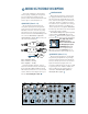
HOOKUP DIAGRAMS 4-track Recorder out (play) in (record) IMPORTANT: ALL Channel Insert plugs are inserted to the SECOND click.
Compressor in out V/O Mic Keyboard or other line-level input 1 2 3 4 R L MONO 8 R R 9 L Audio out R L MONO L 11 MONO 12 R L R in CNTRL ROOM OUTPUTS R L Mackie Designs: Video Setup scene #1 _ 23:94:10 Time Base L R *Note: Aux Return #2 can be used as an extra stereo input 1 L R R 2 Multi Effect Processor in L OUT L out R 2 PHONES Time Code DAT R IN-TAPE-OUT SMPTE Control R L R L 10 R CD Player L 1 Power Amplifier MAIN OUT Video Deck #3 INPUTS Audio out L MO
MORE HOOKUP DIAGRAMS 1 2 Phono Preamps 3 RIAA 4 CD Player 7 L MONO 8 R 9 L R CD Player L out INPUTS L out R CHANNEL 6 MONO 10 R 12 R L R L R 2 Note: Aux Return #2 can be used as an extra stereo input L 1 Triggered Lights Multi Effect Processor org 2 R R L L Stereo EQ OUT CNTRL ROOM OUTPUTS in (record) R PHONES out (play) IN-TAPE-OUT 2-Track Deck L 11 MONO L 1 ALT 3/4 OUT R 3 MAIN OUT out MAIN OUT L Sampler Power Amplifier FULL SYMMETRY DUAL DIFFERENTIA
Vocal Mics 1 2 Line out from Bass Amp 3 3 Bass Effects 4 in out in out 1 CHANNEL INSERTS 1 2 3 L L MONO org 9 L 1 R 2 L R L MONO 10 R L 11 MONO Multi Effect Processor 1 2 L Power Amp Mono EQ R R CH CH 1 2 L R Stereo EQ OUT red Power Amplifier MAIN OUT CNTRL ROOM OUTPUTS in (record) L PHONES out (play) R IN-TAPE-OUT 2-Track Deck L MAIN OUT FULL SYMMETRY DUAL DIFFERENTIAL HIGH CURRENT DESIGN Stage Monitors ,,, 12 R AUX OUT org INPUTS 8 R ALT 3/4 OUT 7
MS1202-VLZ PATCHBAY DESCRIPTION At the risk of stating the obvious, this is where you plug everything in: microphones, line-level instruments and effects, headphones, and the ultimate destination for your sound: a tape recorder, PA system, etc. MIC INPUTS (Channels 1–4) We use phantom-powered, balanced microphone inputs just like the big studio mega-consoles, for exactly the same reason: This kind of circuit is excellent at rejecting hum and noise.
To connect balanced lines to these inputs, use a 1⁄4" Tip-Ring-Sleeve (TRS) plug, the type found on stereo headphones: Another way to consider LOW CUT’s function is that it actually adds flexibility during 0 live performances. With the addition of LOW CUT, you can safely use LOW equalization on Low Cut with Low EQ vocals. Many times, bass shelving EQ can really benefit voices. Trouble is, adding LOW EQ also boosts stage rumble, mic handling clunks and breath pops.
MIC 1 MIC 4 MIC 3 MIC 2 RIGHT LEFT/MONO ALL BAL/UNBAL BAL/UNBAL 1 1 L L LEFT 2 RIGHT R 2 R 60 -40dB 10 +10dB 60 -40dB 10 +10dB 60 -40dB TRIM TRIM TRIM U U U 10 +10dB -10 GA MIC IN -10 GA MIC IN -10 GA MIC IN -10 GA MIC IN U LOW CUT 75 Hz 18dB/OCT LOW CUT 75 Hz 18dB/OCT LOW CUT 75 Hz 18dB/OCT LOW CUT 75 Hz 18dB/OCT STEREO AUX RETURNS LINE IN 4 LINE IN 3 LINE IN 2 LINE IN 1 BAL OR UNBAL BAL OR UNBAL BAL OR UNBAL BAL OR UNBAL 10 +10dB AUX SEND TAPE INPUT TAPE OUT
CHANNEL INSERT (Channels 1–4 ) AUX RETURNS These jacks, on the back of the MicroSeries 1202-VLZ, are where you connect serial effects such as compressors, equalizers, deessers, or filters . Since most people don’t have more than a few of these gadgets, we’ve included inserts for just the first four channels. If you want to use this kind of processing on channels 5 through 12, simply patch through the processor before you plug into the MS1202-VLZ.
MIC 1 MIC 4 MIC 3 MIC 2 RIGHT LEFT/MONO ALL BAL/UNBAL BAL/UNBAL 1 1 L L LEFT 2 RIGHT R 2 R LINE IN 1 LINE IN 2 10 +10dB 60 -40dB TRIM 10 +10dB 60 -40dB TRIM LOW CUT 75 Hz 18dB/OCT -10 GA MIC IN -10 GA MIC IN U U U STEREO AUX RETURNS LINE IN 4 LOW CUT 75 Hz 18dB/OCT -10 GA MIC IN -10 GA MIC IN U LINE IN 3 LOW CUT 75 Hz 18dB/OCT LOW CUT 75 Hz 18dB/OCT BAL OR UNBAL BAL OR UNBAL BAL OR UNBAL BAL OR UNBAL 10 +10dB 60 -40dB TRIM 10 +10dB TAPE INPUT TAPE OUTPUT MAIN
XLR MAIN OUTPUT LEVEL SWITCH Engaging the MAIN OUTPUT LEVEL switch pads the balanced XLR main outputs by 30dB, so you can feed the microphone input of, say, another mixer. You can safely connect this output into an input that provides 48V phantom power. 1⁄4" For most music recording and PA applications, unbalanced lines are perfectly acceptable.
MIC 1 MIC 4 MIC 3 MIC 2 RIGHT LEFT/MONO ALL BAL/UNBAL BAL/UNBAL 1 1 L L LEFT 2 RIGHT R 2 R LINE IN 1 LINE IN 2 10 +10dB 60 -40dB TRIM 10 +10dB 60 -40dB TRIM LOW CUT 75 Hz 18dB/OCT -10 GA MIC IN -10 GA MIC IN U U U STEREO AUX RETURNS LINE IN 4 LOW CUT 75 Hz 18dB/OCT -10 GA MIC IN -10 GA MIC IN U LINE IN 3 LOW CUT 75 Hz 18dB/OCT LOW CUT 75 Hz 18dB/OCT BAL OR UNBAL BAL OR UNBAL BAL OR UNBAL BAL OR UNBAL 10 +10dB 60 -40dB TRIM 10 +10dB AUX SEND TAPE INPUT TAPE OUT
POWER CONNECTION FUSE Just in case you lose the cord provided with the MS1202-VLZ, its power jack accepts a standard 3-prong IEC cord like those found on most professional recorders, musical instruments, and computers. At the other end of our cord is — get this — a plug! Not a black cube or, as we’re fond of calling them, a “wall wart.” We did this for some very good reasons: The MS1202-VLZ has sophisticated power requirements that a wall wart cannot provide.
CHANNEL STRIP DESCRIPTION The eight channel strips look alike, and function identically. The only difference is that the four on the left are for individual mics or mono instruments and have more gain available, while the next four are for either stereo or mono line-level sources. (Each of the stereo channel strips is actually two complete circuits. The controls are linked together to preserve stereo.
else useful… like a separate stereo bus?” So MUTE/ALT 3-4 really serves two functions — muting (often used during a mixdown or live show), and signal routing (for multitrack and live work) where it acts as an extra stereo bus. To use this as a MUTE switch, all you have to do is not use the ALT 3-4 outputs. Then, whenever you assign a channel to these unused outputs, you’ll also be disconnecting it from the MAIN MIX, effectively muting the channel.
LOW EQ This control gives you up to 15dB boost or cut at 80Hz. The circuit is flat (no boost or cut) at the center detent position. This frequency represents the punch in bass drums, bass guitar, fat synth patches, and some really serious male singers. Used in conjunction with the LOW CUT switch , you can boost the LOW EQ without injecting a ton of subsonic debris into the mix.
OUTPUT SECTION DESCRIPTION MAIN MIX As the name implies, this knob controls the levels of signals sent to the main outputs: XLR LEFT and RIGHT , 1⁄4" MAIN OUTS and RCA TAPE OUTPUT . All channels and AUX RETURNS that are not muted or turned fully down will wind up in the MAIN MIX. Fully counterclockwise is off, the center detent is unity gain, and fully clockwise provides 10dB additional gain. This additional gain will typically never be needed, but once again, it’s nice to know it’s there.
Now you know how to select the signals you want to send to the engineer’s control room or phones. From there, these signals all pass through the same level control, aptly named: CONTROL ROOM/PHONES As you might expect, this knob controls the levels of both the stereo CONTROL ROOM outputs and PHONES outputs . The control range is from off through unity gain at the detent, with 10dB of extra gain (when turned fully clockwise).
RUDE SOLO LIGHT This flashing Light Emitting Diode serves two purposes — to remind you that at least one channel is in SOLO, and to let you know that you’re mixing on a Mackie. No other company is so concerned about your level of SOLO awareness. If you work on a mixer that has a solo function with no indicator lights, and you happen to forget you’re in solo, you can easily be tricked into thinking that something is wrong with your mixer. Hence the RUDE SOLO LIGHT.
AUX 1 SELECT (MON/PRE or POST) AUX TALK First of all, there is no particular alliance between AUX SEND 1 (or 2) and AUX RETURN 1 (or 2). They’re just numbers. They’re like two complete strangers, both named Fred. Sends are outputs, returns are inputs. The AUX knob taps the signal off the channel and sends it to the AUX SEND outputs . The AUX 1 signal is sent to the AUX 1 MASTER knob before going to the AUX SEND 1 output and the AUX 2 signal goes directly to the AUX SEND 2 output.
AUX RETURNS These two controls set the overall level of effects received from STEREO AUX RETURN inputs 1 and 2 . These controls are designed to handle a wide range of signal levels, from off, to unity gain at the detent, with 20dB gain fully clockwise, to compensate for low-level effects. Typically, these knobs can just live at the center detent, and the effects device’s output control should be set at whatever they call unity gain (check their manual).
MODIFICATIONS For most folks, the MS1202-VLZ works just fine the way it is. But for special applications, there are three signal routing changes that can be performed easily on the MS1202-VLZ. Easy for someone with soldering experience, that is. If you don’t know how to solder, find a technician that can. This is NOT a good place to learn! • Modification A changes AUX SEND 2 to be pre-fader, pre-mute instead of post-fader, post-mute.
2. PRE-MUTE MOD This modification changes AUX SEND 1 (in post mode) and AUX SEND 2 to receive signal regardless of the channel’s MUTE/ALT 3-4 switch position, but still be post-fader (GAIN knob). In order to convert the entire mixer, it must be done on each channel. It is slightly more involved for the stereo channels 5 through 12. The work area is on the underside of the circuit board, near the channel MUTE/ ALT 3-4 switches. 1. Remove all cords, including the power cable, from the MS1202-VLZ. 2.
3. MAIN MIX SOURCE MOD This modification changes the SOURCE matrix’s MAIN MIX selection to tap the stereo signal before the MAIN MIX level control (pre) instead of after (post). This could be especially handy for live work where the engineer wants to be able to control the MAIN MIX level (sent to the house system) without changing the level in his headphones. The work area is on the underside of the circuit board, near the MAIN MIX level control.
LINE IN MIC IN 1 3 2 TRIM LINE IN R LO CUT MACKIE MS1202-VLZ BLOCK DIAGRAM (MS-0808.VSD) Version 2.
LINE IN, Channels 5-12 Unity gain +22dBu max in LINE IN, Channels 1-4 40dB gain, TRIM up 10dB loss, TRIM down +22dBu max in MIC IN, Channels 1-4 60dB gain, TRIM up 10dB gain, TRIM down +14dBu max in 0dB 0dB 0dB to 'A' to 'A' to 'A' 'A' 0dB +10dB up PAN AUX SEND Channel AUX SEND AUX MIX OUTPUT 0dB OUTPUT 0dB +22dBu max out Master AUX SEND +10dB up to 'C' 'C' +22dBu max out -4dB center CONTROL ROOM / PHONES +15dB up SOURCE Matrix TAPE IN 6dB Boost GAIN 'B' C-R/PHONES
SPECIFICATIONS Main Mix Noise Common Mode Rejection (CMR) 20Hz–20kHz bandwidth, 1/4" Main out, channels 1–4 Trim @ unity gain, channel EQs flat, all channels assigned to Main Mix, channels 1 and 3 Pan left, 2 and 4 Pan right. Mic in to Insert Send out, max gain Main Mix knob down, channel Gain knobs down: –100dBu Main Mix knob unity, channel Gain knobs down: –86.5dBu (90dB Signal to Noise Ratio, ref +4dBu) Main Mix knob @ unity, channel Gain knobs @ unity: –84.5dBu Total Harmonic Distortion (THD) 0.
SERVICE INFO Details concerning Warranty Service are spelled out on the Warranty Card included with your mixer (if it’s missing, let us know and we’ll rush one to you). If you think your MS1202-VLZ has a problem, please do everything you can to confirm it before calling for service. Doing so might save you from the deprivation of your mixer and the associated suffering.
APPENDIX A: GLOSSARY This Glossary contains brief definitions of many of the audio and electronic terms used in discussions of sound mixing and recording. Many of the terms have other meanings or nuances or very rigorous technical definitions which we have sidestepped here because we figure you already have a lot on your mind. If you’d like to get more information, you can call Mix Bookshelf at 1-800-233-9604.
condenser dBV Another term for the electronic component generally known as a capacitor. In audio, condenser usually refers to a type of microphone that uses a capacitor as the sound pickup element. Condenser microphones require electrical power to run internal amplifiers and maintain an electrical charge on the capacitor. They are typically powered by internal batteries or “phantom power” supplied by an external source, such as a mixing console.
dynamic In sound work, dynamic refers to the class of microphones that generate electrical signals by the movement of a coil in a magnetic field. Dynamic microphones are rugged, relatively inexpensive, capable of very good performance and do not require external power. dynamic range The range between the maximum and minimum sound levels that a sound system can handle. It is usually expressed in decibels as the difference between the level at peak clipping and the level of the noise floor.
filter graphic EQ A simple equalizer designed to remove certain ranges of frequencies. A low-cut filter (also called a high-pass filter) reduces or eliminates frequencies below its cutoff frequency. There are also high-cut (low-pass) filters, bandpass filters, which cut both high and low frequencies but leave a band of frequencies in the middle untouched, and notch filters, which remove a narrow band but leave the high and low frequencies alone.
Haas effect knee A psychoacoustic effect in which the time of arrival of a sound to the left and right ears affects our perception of direction. If a signal is presented to both ears at the same time at the same volume, it appears to be directly in front of us. But if the signal to one ear, still at the same volume, is delayed slightly (0 to 5 msec), the sound appears to be coming from the earlier (non-delayed) side. A knee is a sharp bend in an EQ response curve not unlike the sharp bend in your leg.
mixer noise floor An electronic device used to combine various audio signals into a common output. Different from a blender, which combines various fruits into a common libation. The residual level of noise in any system. In a well designed mixer, the noise floor will be a quiet hiss, which is the thermal noise generated by bouncing electrons in the transistor junctions. The lower the noise floor and the higher the headroom, the more usable dynamic range a system has.
Generally, phantom power is safe to use with non-condenser microphones as well, especially dynamic microphones. However, unbalanced microphones, some electronic equipment (such as some wireless microphone receivers) and some ribbon microphones can short out the phantom power and be severely damaged. Check the manufacturer’s recommendations and be careful! phasing A delay effect, where the original signal is mixed with a short (0 to 10 msec) delay.
return shelving A return is a mixer line input dedicated to the task of returning processed or added sound from reverb, echo and other effects devices. Depending on the internal routing of your mixer and your own inclination, you could use returns as additional line inputs, or you could route your reverb outputs to ordinary line inputs rather than the returns. A term used to describe the shape of an equalizer’s frequency response.
tinnitus The ringing in the ears that is produced with prolonged exposure to high volumes. A sound in the ears, such as buzzing, ringing, or whistling, caused by volume knob abuse! trim In audio mixers, the gain adjustment for the first amplification stage of the mixer. The trim control helps the mixer cope with the widely varying range of input signals that come from real-world sources.
APPENDIX B: CONNECTIONS “XLR” CONNECTORS Mackie mixers use 3-pin female “XLR” connectors on all microphone inputs, with pin 1 wired to the grounded (earthed) shield, pin 2 wired to the “high” (”hot” or positive polarity) side of the audio signal and pin 3 wired to the “low” (“cold” or negative polarity) side of the signal (Figure 2 SHIELD A).
RCA PLUGS AND JACKS SPECIAL MACKIE CONNECTIONS RCA-type plugs (also known as phono plugs) and jacks are often used in home stereo and video equipment and in many other applications (Figure D). They are unbalanced and electrically identical to a 1⁄4" TS phone plug or jack (See Figure C). Connect the signal to the center post and the ground (earth) or shield to the surrounding “basket.” The balanced-to-unbalanced connection has been anticipated in the wiring of Mackie jacks.
If you push the 1⁄4" TS plug in to the second click, you will open the jack switch and create a direct out, which does interrupt the signal in that channel. See Figure E. NOTE: Do not overload or short-circuit the signal you are tapping from the mixer. That will affect the internal signal. MACKIE STEREO INPUTS AND RETURNS: Mono, Stereo, Whatever A stereo signal, having two plugs, should be patched into the LEFT (MONO) and the RIGHT input or return jacks.
APPENDIX C: Balanced Lines, Phantom Powering, Grounding and Other Arcane Mysteries Balanced Lines What is it, exactly? Balanced lines offer increased immunity to external noise (specifically, hum and buzz). Because a balanced system is able to minimize noise, it is the preferred interconnect method, especially in cases where very long lengths of cable are being used.
PHANTOM POWER DO & DON’T CHART DO DON’T If you are plugging in a condenser microphone, do verify that your microphone can be phantom powered. Don't worry about your other microphones as long their outputs are balanced and floating. Ensure that the microphone’s output is low impedance, balanced and floating. This is especially important for vintage ribbon microphones like the RCA 44BX and 77DX. Don't connect microphones or devices that do not conform to the DIN 45 596 standard.
Do’s and Don’ts of Fixed Installations If you install sound systems into fixed installations, there are a number of things that you can do to make your life easier and that increase the likelihood of the sound system operating in a predictable manner. Even if you don’t do fixed installations, these are good practices for any sound system, installed. 1. Do use foil-shielded snake cable for long cable runs. Carefully terminate each end, minimizing the amount of shielding removed.
Many “authorities” tell you that shields should only be connected at one end. Sometimes this can be true, but for most (99%) audio systems, it is unnecessary. If you do everything else correctly, you should be able to connect every component of your audio system using standard, off-the-shelf connecting cables that are available at any music store. Here are some guidelines: 1. All return lines to the stage should be balanced. At a minimum, they should be impedance balanced.
MIC 1 MIC 4 MIC 3 MIC 2 MICRO SERIES 1202-VLZ 12-CHANNEL MIC/LINE MIXER Session: Date: 1 L MONO MONO L L L L BAL OR UNBAL BAL OR UNBAL BAL OR UNBAL BAL OR UNBAL R R R R LEFT 2 RIGHT R 2 R STEREO AUX RETURNS AUX SEND U U 60 -40dB 10 +10dB LINE IN 5-6 TRIM TRIM TRIM TRIM 60 -40dB 10 +10dB 60 -40dB 10 +10dB 60 -40dB 10 +10dB MONO U U U U -10 C GAIN MI -10 C GAIN MI -10 C GAIN MI -10 C GAIN MI LOW CUT 75 Hz 18dB/OCT LOW CUT 75 Hz 18dB/OCT LOW CUT 75 Hz 18dB
Some of the people at our Woodinville, Washington factory who helped design, build, sell, and support your product. ® ® ™ ® Mackie Designs Inc. 16220 Wood-Red Rd. NE • Woodinville, WA 98072 • USA 800/898-3211 • Outside the US: 425/487-4333 Fax: 425/487-4337 • www.mackie.com E-mail: sales@mackie.